HOW-TO GUIDE
Why Does My Multimeter Read 0 Volts on a Working Circuit?
By the OhmSavvy Research Team ·

Safety: treat a 0 V reading as unproven
- Never assume a circuit is dead because the meter shows 0 V. Every cause on this page, from a broken lead to HOLD mode, can show zero on a live conductor. Prove the meter on a known live source before and after you test.
- On mains, use a meter and leads rated for the location: CAT III 600V or better for household branch circuits and panels. Keep your fingers behind the probe guards.
- Never bypass or bridge a fuse, in the meter or in the circuit, to get a reading. Panel and fixed wiring faults are work for a licensed electrician.
What a zero reading actually says
A voltmeter never measures the voltage "at" a point. It measures the difference between whatever the red probe touches and whatever the black probe touches. Zero is therefore a perfectly honest answer in several situations: when the two probes share the same conductor, when there is no connection between the black probe and the part of the circuit the red probe is on, and when the section you are testing has genuinely lost its supply. Only one of those means the device is faulty.
The other group of zeros comes from the meter side. The signal never reaches the display because a lead is broken inside its insulation, the red lead is in a current jack, the display is frozen by HOLD, a REL offset is canceling the reading, or the function is set to the wrong kind of voltage. These are worth ruling out first because they take seconds and they are invisible: a broken lead looks exactly like a good one.
This page deals with the flat 0 or 0.00 case. If your meter shows a number that is merely too high, too low, or the wrong sign, our guide to why a multimeter shows the wrong voltage covers range errors, True RMS limits and loading, and negative voltage readings have their own explainer.
Causes at a glance
| Symptom | Likely cause | How to check | Fix |
|---|---|---|---|
| 0.00 V on a lit lamp or running motor | Both probes on the same node | Are the two points joined by plain wire, with no source or load between them? | Move one probe so a source or load sits between the probes |
| 0 V, or a few mV that wander | Black lead has no reference (floating section, wrong ground, painted chassis) | With power off, check continuity from the COM contact point to supply negative | Clip COM to the supply's own negative or a known good ground |
| Near 0 on a battery or DC rail | Dial on V AC with a DC source | Look for AC, DC or ~ beside the digits | Select V DC, or use auto AC/DC if the meter has it |
| Near 0 on an outlet or transformer | Dial on V DC with an AC source | Same display check | Select V AC |
| 0 V everywhere, including a fresh AA | Open test lead or broken probe wire | Short the tips on continuity: OL or flicker means a break | Replace the lead set |
| 0 V everywhere, leads test fine | Red lead in the A or mA jack | Check which jack the red plug sits in | Move it to the V jack, then check the current fuse |
| Display stuck at 0 and does not change | HOLD engaged | Look for an H or HOLD icon | Press HOLD to release |
| Shows 0.00 on a source that read correctly a moment ago | REL or delta offset stored | Look for REL or a delta symbol | Press REL again or cycle the dial |
| 0 V on known sources, other functions work | Damaged voltage input, often after an overload | Known-source test with good leads and a fresh battery | Have the meter repaired or replace it |
| 0 V at one point, correct voltage nearer the source | Section genuinely unpowered: open fuse, switch, connector, regulator | Measure from the source outward until the voltage disappears | Repair the open point you found |
1Verify on a known source
Before you touch the circuit again, prove the meter. Set it to V DC, plug the black lead into COM and the red lead into the V jack, and measure a fresh alkaline AA cell: red on the button end, black on the flat end. A new AA typically reads about 1.5 to 1.6 V; a used one reads lower but never zero unless it is completely flat. A 9 V battery or a USB charger (about 5 V between the outer pins) works too. If you work on mains, also check a known-good outlet on V AC.
This single test splits the problem in half. A correct reading on the cell means the meter is fine and the zero is about where you are probing, so skip to step 4. A zero on the cell means the circuit was never the problem, and steps 2 and 3 will find the cause.
2Check the leads and jacks
Test leads fail more often than meters. The fine copper strands break where the cable flexes most, at the probe handle and at the banana plug, and the insulation hides the break completely. Turn the dial to continuity or the lowest ohms range and touch the probe tips together: a good set beeps and reads a fraction of an ohm. OL means one conductor is open. If it beeps only some of the time, flex each cable along its length while watching the display; the reading will drop out at the break. The meaning of that OL display is explained in our guide to what OL means on a multimeter.
Then look at the jacks. Voltage is measured with the red lead in the jack marked V (often shared with Ω and the diode symbol). If the red lead is in the A or mA jack, most meters show zero on the voltage function, because the voltage input is no longer connected to anything. Worse, the current jack connects your probes through a very low resistance, so touching a battery or outlet in that state shorts it through the meter.
This is also the only situation where a blown meter fuse matters for voltage. On most meters the internal fuses sit only in the current paths, behind the mA and A jacks, and the V input never passes through them. A meter with a blown current fuse will still read volts correctly with the red lead in the V jack. If your fuse has gone, our article on why a multimeter fuse blows when measuring current explains what caused it and how to choose the correct replacement.
3Rule out HOLD, REL and the wrong mode
HOLD freezes the display at the last value, which is often 0.00 if you pressed it before connecting the probes. The tell is an H or HOLD icon and a display that does not move at all, not even by one digit, as you move the probes. REL (relative, sometimes a delta symbol) is subtler: it stores the present reading and subtracts it from everything after. Press it by accident while measuring 12 V and that 12 V now displays as 0.00. Both buttons sit close to the dial on most meters and are easy to nudge. Our multimeter symbols guide shows what each icon looks like.
AC versus DC. On the DC function a meter reports the average of the signal. A pure sine wave spends equal time above and below zero, so its average is essentially zero, and an outlet measured on V DC can sit at or near 0. Point the AC function at a steady battery and many meters show 0 or a few millivolts for the opposite reason: the AC function looks for a changing signal and ignores the steady part. The AC vs DC voltage guide explains the difference. On a meter with automatic AC/DC selection the mistake mostly disappears; the Fluke 117's AutoVolt feature, which the Fluke 115 lacks, selects AC or DC for you.
Range. On a manual-ranging meter, a range far above the signal can round a small voltage down to zero: 0.04 V on a 600 V range has no digit to show up in. Drop to the lowest range that does not show OL, or let an auto-ranging meter settle for a second before you read it.
4Fix the probe placement
Once the meter reads a known source correctly, a zero on the circuit is about the two points you chose. In the diagram below, the battery drives current through a closed switch and a lamp. The meter across A and G spans the battery, so it reads the full 12 V. The second meter has both probes on the return wire, C and G. That wire has almost no resistance and carries the same current everywhere, so the voltage drop along it is a few millivolts at most, and the meter shows 0.00. The lamp is lit and the circuit works; the probes simply have nothing between them.
The same thing happens across any closed switch, any intact fuse and any short length of wire. In fact, 0 V across a closed switch or a good fuse with current flowing is the correct, healthy result; the full supply voltage across them would mean they are open. That is the basis of testing a fuse in place, described in our guide to testing a fuse without removing it.
The opposite mistake is a black probe with no reference at all. In an isolated section, such as the secondary of a transformer, the output of an isolated DC-DC converter, a floating battery pack, or a chassis bracket insulated by paint, the black probe touches metal that has no connection to the circuit the red probe is on. With no complete path for the meter's tiny input current, the reading sits at zero or drifts around a few millivolts. In a car, clip COM to the battery negative terminal or a clean, unpainted engine bolt; on a circuit board, clip it to the supply's own ground pin, not to the metal case. If you see a wandering number instead of a flat zero, the symptoms overlap with those in unstable multimeter readings.
5Trace the real 0 V upstream
Sometimes the meter is right and the section really is dead. A device can "work" while one part of it has no power: a blown fuse on one branch, a relay that never closed, a voltage regulator held off by its enable pin, a connector pushed half home, or one leg of a split supply that has failed. The radio plays but the dash light circuit is dead; the board's LED glows but the 3.3 V rail reads zero.
01
Source
Full voltage at the supply?
02
Protection
Both sides of the fuse
03
Control
Switch, relay, regulator
04
Load
Find where it drops to 0
Keep the black probe on one solid reference and walk the red probe outward from the source: supply output, then each side of the fuse, then each side of the switch or relay contacts, then the connector pins, then the load. The voltage is present up to a certain point and gone after it. The open part is between your last good reading and your first zero. For a car fuse that shows power on one side only, our walkthrough on power on one side of a car fuse follows that exact path.
Why does my multimeter show 0 volts when the power is on?
When a multimeter reads 0 volts while the power is on, the switch being on does not guarantee that voltage reaches the two points you are touching. Either the probes are not making electrical contact, the output you are probing is switched off at that instant by something other than the main switch, or you are measuring across a part that should have no voltage across it while it conducts. Work through these powered-circuit cases after the meter has passed the AA test in step 1.
- The probe tip never touched metal. Corrosion on a battery post, paint on a terminal screw, the plastic shroud of a sealed automotive connector, or the clear conformal coating on many circuit boards all insulate the tip from the conductor underneath. Press firmly, scrape a small spot on the terminal, or use sharp tips or back-probe pins designed for sealed connectors. Never pierce wire insulation on a mains circuit.
- Tamper-resistant outlet shutters. Newer US receptacles have spring shutters behind the slots that generally open only when both blades push in together. A single probe in one slot can stop against the shutter and read 0 V on a live outlet. Insert both probes at the same time, hot slot and neutral slot, with fingers behind the guards, or measure at a plug-in tester.
- The output is controlled, not just powered. A relay that waits for a thermostat or a module command, a PWM-driven fan or LED strip, and a car circuit that only switches on with the key in RUN can all sit at 0 V while the system is "on." Measure while the function is actually commanded on, and on a pulsed output expect an average voltage that changes with the duty cycle rather than a steady supply value. Our relay testing guide covers checking the coil and contacts separately.
- A protective device upstream has opened. The house has power but one outlet is fed through a tripped GFCI somewhere else on the circuit, or one branch in a car has a blown fuse. The zero is genuine. A GFCI that will not reset has its own walkthrough in testing a GFCI outlet that won't reset.
- You are measuring a voltage drop, not a supply. With the power on and current flowing, a closed switch, relay contact, intact fuse or length of wire should show close to zero across it. That is the healthy result of a voltage-drop test, not a missing supply.
The chart shows how large those drops are next to the supply in the 12 V lamp circuit from the diagram. The small values are illustrative but realistic orders of magnitude: tens of millivolts across good contacts and fuses, nearly the whole supply across the working load, and the whole supply across a switch only when it is open. On an auto-ranging meter those tens of millivolts often display as 0.0 or 0.00 on a volts range, which is why a healthy closed switch looks like "no power."
If you need to see those small drops rather than a rounded zero, select the mV range: a closed switch reading several hundred millivolts under load is a worn contact, even though it still passes enough current to run the load. For a car, our guide to checking voltage drop on a car gives the limits to compare against.
Probe placement and expected readings
Using the 12 V circuit in the diagram, this is what a healthy meter should show at each pair of points, with the switch closed and then open. Notice how many of the correct answers are zero. The values are idealized: real wiring drops a little voltage, so expect a few millivolts where the table says 0 and slightly under 12 V across the lamp.
| Red probe | Black probe | Switch closed (lamp on) | Switch open (lamp off) | Why |
|---|---|---|---|---|
| A (battery +) | G (battery −) | 12 V | 12 V | Spans the source; always reads the battery |
| B (after switch) | G | 12 V | 0 V | Switch open: B is cut off from the supply |
| A | B (across switch) | 0 V | 12 V | A closed switch has no drop; an open one has it all |
| B | C (across lamp) | 12 V | 0 V | The load drops the voltage only while current flows |
| C | G (same return wire) | 0 V | 0 V | Same node: no potential difference in either state |
| A | Painted bracket (no connection) | 0 V or drifting mV | 0 V or drifting mV | Black probe has no reference to the circuit |
Zero is a difference, not a level
Meters for live troubleshooting
Any working meter will show the zeros described here; what changes is how easily you can trust it. These picks come from our verified multimeter list.
Meters from our verified picks
True RMS, CAT III 600V, auto-ranging, with built-in NCV detection. Hands-on Tested.

CAT III 1000V / CAT IV 600V, 19,999-count high-resolution mode and an analog bar graph. Hands-on Tested.
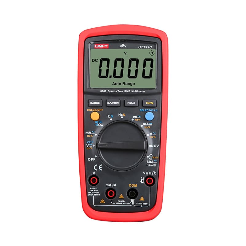
Budget True RMS, 6,000-count, CAT III 600V, with auto and manual ranging and NCV.
As an Amazon Associate I earn from qualifying purchases. Prices and availability are shown on Amazon.
Frequently asked questions
Why does my multimeter show 0 volts when the power is on?
Prove the meter on a fresh AA first. If that reads correctly, the probes are either not touching bare metal (paint, corrosion, a sealed connector or board coating), the output you are probing is switched off by a relay, module or upstream GFCI, or you are measuring across a closed switch or good fuse, where near 0 V with current flowing is the healthy result.
Why does my multimeter read 0 volts on an outlet that works?
On many newer US outlets, tamper-resistant shutters behind the slots open only when both prongs push in together, so a single probe can stop against the shutter and read zero. Insert both probes at once into the hot and neutral slots, keep your fingers behind the guards, and confirm the dial is on V AC. If it still reads zero, stop and call an electrician.
Why does my multimeter read 0 volts but the light is on?
If the lamp is lit, voltage is present across it, so a 0 V reading means the probes are not spanning the lamp or the supply. The most common reason is that both probes sit on the same wire, such as two points on the return conductor. Put the red probe on the feed side and the black probe on the return side, and the reading should appear.
Can a blown fuse in my multimeter cause a 0 volt reading?
Usually not. On most meters the internal fuses protect only the mA and A jacks, and the voltage input does not pass through them. A blown current fuse affects voltage readings only if the red lead is plugged into a current jack by mistake. If the meter reads 0 V on every source with the red lead in the V jack, suspect the leads or the input circuit instead.
Why does my multimeter read 0 on DC but shows a voltage on AC?
On the DC function the meter averages the signal. A pure AC waveform averages to almost nothing, so a wall outlet or transformer secondary can read near 0 V DC while reading the full value on V AC. The reverse can also happen on some meters. Check the AC or DC indicator on the display and match it to the source before trusting any reading.
How do I know if my multimeter leads are broken?
Set the meter to continuity or the lowest ohms range and touch the probe tips together. Healthy leads beep and read a fraction of an ohm. OL, or a reading that jumps when you flex the cable near the probe or the plug, means a broken conductor. Wiggle each lead along its length while watching the display; the break is usually near a strain relief.
Why does my multimeter show 0.00 after I press the REL button?
REL (relative, often shown as a delta symbol) stores the current reading and subtracts it from everything that follows. If you pressed it while measuring a voltage, that voltage becomes the new zero and the display shows 0.00 or close to it. Press REL again, or turn the dial off and on, to clear the stored offset and return to absolute readings.
Where should I put the black probe when testing voltage in a car?
On a known good ground: the battery negative terminal is the most reliable, and a clean, unpainted chassis or engine bolt usually works. Paint, rust or a floating bracket can give 0 V or a low, wandering reading even on a live circuit. If a reading looks wrong, move the black probe directly to battery negative and measure again before suspecting the circuit.
Where to go next
Why Does My Multimeter Show the Wrong Voltage? →
Readings that are off rather than zero: range, True RMS, loading and calibration.
Why Does a Multimeter Fuse Blow When Measuring Current? →
What a lead left in the amps jack does to the meter, and how to replace the fuse.
What Causes Unstable Multimeter Readings? →
When the number jumps around instead of sitting at zero.

