HOW-TO GUIDE
How to Measure Resistance in a Parallel Circuit
By the OhmSavvy Research Team ·

Power off and discharge before measuring resistance
Why parallel resistance reads "wrong"
A multimeter in resistance mode sends a small test current out one probe and measures how much comes back through the other, calculating resistance from that. It has no way to know which path you intended to test — it simply measures the total resistance of every path that exists between the two probe points. If a resistor sits in parallel with others, all of those other paths are part of what the meter measures, not just the one resistor.
The parallel resistance formula
For any number of resistors in parallel, the combined resistance follows:
1 / R(total) = 1 / R1 + 1 / R2 + ... + 1 / Rn
Two different goals, two different methods
| What you actually want | Method |
|---|---|
| The combined resistance of the parallel group | Measure directly across the shared nodes — no isolation needed |
| One specific resistor's own value | Isolate it (lift one leg) before measuring |
1Measuring the combined parallel resistance
If what you actually need is the overall resistance the parallel group presents to the rest of the circuit — for troubleshooting or verifying a design — simply touch the probes to the two shared nodes the parallel resistors connect between, with the circuit unpowered. No isolation is needed here, because the combined reading is exactly what you want.
2Measuring one resistor's own value
To confirm a specific resistor's own value — checking it against its color-code or verifying it hasn't drifted — isolate it from the rest of the circuit first. Lifting one leg out of its hole or pad breaks the parallel path through it while leaving everything else connected, then measure across its two leads directly.
3Always de-energize the circuit first
Switch off and unplug any power source, and discharge capacitors before measuring resistance in either scenario above. This protects both the meter and the accuracy of the reading, since any external voltage present during a resistance measurement corrupts the result.
Worked example
Two resistors, 100Ω and 220Ω, wired in parallel: 1/R = 1/100 + 1/220 = 0.01 + 0.00455 = 0.01455, so R = 1 / 0.01455 ≈ 68.7Ω. Measuring directly across the shared nodes should read close to 68.7Ω. If you instead lift one leg of the 100Ω resistor and measure across just its own leads, you should read close to 100Ω on its own.
Three resistors: visualizing the drop
Adding a third resistor in parallel only pulls the combined value down further. With 100Ω, 220Ω, and 330Ω all in parallel: 1/R = 1/100 + 1/220 + 1/330 ≈ 0.01758, so R ≈ 56.9Ω — lower than any single resistor in the group, including the smallest one.
Meters that resolve small resistance differences
Telling a 68.7Ω parallel pair from a 100Ω resistor on its own is easy on any digital meter, but spotting a few percent of drift in a combined value needs a display with enough counts. All three below have 6,000-count displays; the cheapest suits bench electronics, the Flukes suit mixed electrical and electronics work.
Meters for resistance work
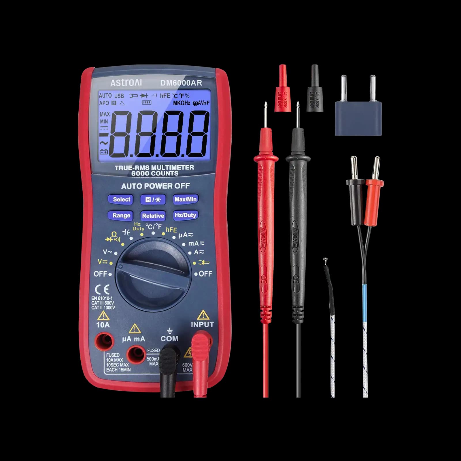
6,000-count True RMS with both auto and manual ranging. No CAT rating stated, so keep it to low-voltage circuit boards.

6,000-count backlit display, CAT III 600V, with capacitance and frequency. Hands-on Tested.
The 115's measurement core plus NCV and LoZ for household wiring. Hands-on Tested.
As an Amazon Associate I earn from qualifying purchases. Prices and availability are shown on Amazon.
Frequently asked questions
Why is my resistance reading lower than the resistor's printed value?
This is the classic sign of an unintended parallel path. If the reading is lower than expected, a second route for current exists between your probes — another resistor, a wire, or another component in parallel with the one you're testing. Combined parallel resistance is always lower than the smallest individual resistance in the group.
If one resistor is much smaller than the others, does it dominate the combined reading?
Yes — when one parallel resistor is much lower in value than the rest, the combined resistance ends up close to that smallest resistor's own value, since it offers by far the easiest path for current. A 10Ω resistor in parallel with a 10kΩ resistor reads close to 10Ω combined, not somewhere in between the two.
Can I measure parallel resistance with the circuit powered on?
No — resistance mode works by sending the multimeter's own small test current through the circuit and measuring the voltage that results. An externally powered circuit adds its own voltage on top, giving a meaningless or wrong reading, and on many meters can trip overload protection or damage the meter. Always de-energize and discharge capacitors first.
Do I need to fully remove a resistor to test it individually?
Not always — lifting just one leg out of the board or breadboard is usually enough, since that breaks the parallel path through that resistor while leaving the rest of the circuit otherwise intact. Full removal is only needed if lifting a leg isn't practical for the way the component is mounted.
Does this same issue apply to measuring voltage or current in a parallel circuit?
No, it's specific to resistance. Voltage is measured in parallel across any two points you choose, including an individual resistor, without disturbing the circuit, since the meter's voltage input is high-impedance. Current, on the other hand, must be measured in series within the specific branch you care about, which is a different complication from this one.

