HOW-TO GUIDE
How to Measure Voltage on a Floating Ground Circuit
By the OhmSavvy Research Team ·
What phantom voltage actually is
Phantom (or "ghost") voltage is a real reading on the meter's display that doesn't represent a usable, driven voltage source. It shows up specifically on points that are floating — not intentionally tied to a defined reference — and it's one of the most common sources of confusing, seemingly-impossible multimeter readings for anyone troubleshooting wiring.
Why high input impedance causes this
A modern digital multimeter is deliberately built with very high input impedance (commonly 10 megohms or more) so that connecting it to a circuit doesn't meaningfully load that circuit down — exactly the property that makes voltage measurement across a resistor non-invasive. The same property means that even a tiny induced or leakage current, far too small to do anything useful, can produce a full-looking voltage reading across that high impedance. A genuinely driven circuit, by contrast, can sustain that voltage under an actual load.
A worked example: why the number collapses
Think of the coupling between the live wire and the floating wire as a very large impedance in series with the meter, forming a voltage divider. The numbers below are illustrative, not measurements: say the coupling acts like 10 MΩ from a 120V conductor. A standard meter with a 10 MΩ input forms an even split, so it reads 120 × 10 ÷ (10 + 10) = 60V. Swap in a low-impedance input of a few kilohms, say 3 kΩ, and the same divider gives 120 × 0.003 ÷ (10 + 0.003) ≈ 0.04V. A real, driven conductor has a source impedance of a fraction of an ohm, so it reads close to the full 120V on either setting.
That difference is the whole diagnostic: a floating wire's reading depends heavily on the meter's input impedance, while a real source's reading barely moves. Real coupling values depend on cable length, spacing and frequency, so the phantom number you see can be anything from a few volts to most of the supply voltage.
1Measure between the actual two points, not an assumed ground
Where possible, measure directly between the two specific points you actually care about, rather than referencing an assumed common ground that may not genuinely be shared between them. This sidesteps the floating-reference problem entirely for many situations.
For example, on an isolated battery-powered board, put the black probe on that board's own negative rail rather than on a bench ground or a nearby metal case. On an isolated power supply output, measure directly across its plus and minus terminals. If the two points you need to compare genuinely sit in different systems, measure each one against its own reference and compare the results instead of probing straight between them.
2Add a small load to collapse a phantom reading
Connecting a known resistor (or a simple test light / solenoid-style tester) in parallel with the multimeter draws enough current to collapse a true phantom voltage toward zero, since the tiny source behind it can't sustain real current under even a modest load. A genuinely live, driven voltage barely changes under the same small load.
3Use low-impedance (LoZ) mode if your meter has it
Some meters built for electrical troubleshooting include a dedicated LoZ setting that temporarily lowers the meter's own input impedance for exactly this situation, making phantom voltage readings collapse automatically without needing a separate load resistor. Check your meter's dial or manual for this option.
When in doubt, treat the reading as real
Quick reference
| Observation | Likely explanation |
|---|---|
| Disconnected wire reads a specific-looking voltage (e.g. 60V, 110V) | Phantom voltage from nearby capacitive coupling |
| Reading collapses to near-zero under a small load | Confirms it was phantom voltage, not a real source |
| Reading barely changes under a small load | Genuine, driven voltage — treat as live |
| Two separate systems read an odd voltage between them | No shared ground reference between the two — floating, not necessarily faulty |
The core idea
Meters with LoZ mode
If you chase ghost voltages often, a meter with a built-in low-impedance mode saves carrying a load resistor and gives a cleaner yes-or-no answer. These picks from our reviews list LoZ in their maker's specs. Note that LoZ mode briefly loads the circuit, so don't use it on sensitive electronics or control signals that a few kilohms could disturb.
Meters that can rule out phantom voltage

Hands-on tested. True RMS, CAT III 600V, with AutoVolt, LoZ and non-contact voltage built in.

CAT IV 600V / CAT III 1000V, 6,000-count True RMS, with a LoZ mode for ghost voltages.
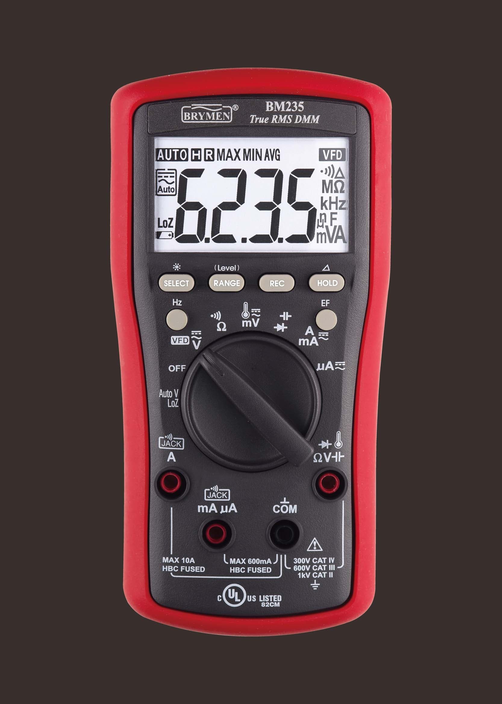
True RMS and 6,000-count, with AutoV low-impedance voltage, NCV and a VFD mode.
As an Amazon Associate I earn from qualifying purchases. Prices and availability are shown on Amazon.
Frequently asked questions
Is phantom voltage dangerous?
Phantom voltage itself can't deliver meaningful current, so it generally can't shock you or power a load — but you can't tell a phantom reading apart from a genuinely live, dangerous wire just by looking at the number on the display. Always treat any unexpected voltage reading as potentially real until proven otherwise with one of the techniques on this page.
Why does a disconnected wire still show 60V or 110V on my meter?
Those specific-looking numbers are a classic sign of capacitive coupling from a nearby live conductor (often another wire in the same conduit or bundle) inducing a small current into the floating wire. A true multimeter has such high input impedance that this tiny induced current is enough to show a voltage reading, even though almost no real current is available.
Does every multimeter have a LoZ mode?
No — it's a feature found mainly on meters marketed toward electricians, not a universal multimeter function. Check your specific meter's manual or dial markings; if it isn't available, the load-resistor method works on any standard multimeter instead.
Can I just trust a non-contact voltage tester instead?
A non-contact tester is a useful cross-check, since it detects an electric field rather than relying on a floating reference point the way a standard multimeter probe does. It's best used alongside a multimeter reading, not as a complete replacement, since non-contact testers can also occasionally give false readings from nearby fields.
Why does my car or solar circuit read voltage between two grounds that should be the same?
Ground wires and chassis paths have resistance, and current flowing through them creates a small voltage difference. A reading of a few tenths of a volt between two ground points while a load runs usually means a corroded strap or loose bolt, not a floating circuit. Unlike phantom voltage, this reading appears only under load and doesn't collapse when you add a test load.


