HOW-TO GUIDE
Why Does My Electronic Circuit Draw Too Much Current? How to Troubleshoot It
By the OhmSavvy Research Team ·
Limit the energy before you look for the fault
- A board that draws too much current can heat a part quickly enough to burn fingers, crack a package or split a capacitor. Keep your face away from the board on first power-up and wear eye protection.
- Don't try these methods on mains-powered circuits unless you are trained to do so. Work on the low-voltage side, powered from a bench supply or batteries.
- Lithium batteries can deliver tens of amps into a short. Never use one as the supply while hunting a fault; use a current-limited bench supply instead.
- Polarized electrolytic and tantalum capacitors fitted backwards can vent or ignite. Disconnect power at the first sign of smoke or a smell of burning.
Causes at a glance
| Symptom | Likely cause | How to check | Fix or who to call |
|---|---|---|---|
| Supply in CC at once, rail near 0 V | Shorted decoupling or bulk capacitor | Rail-to-ground ohms with power off; hot spot at low limit | Replace the capacitor |
| Part hot within seconds of power-up | Polarized part fitted backwards | Check orientation marks on electrolytics, tantalums, diodes, ICs | Refit the right way; replace if stressed |
| High draw on a newly built board | Solder bridge | Inspect fine-pitch pins under magnification; beep pin to pin | Remove with flux and wick |
| Regulator very hot; output wrong | Failed or overloaded regulator | Measure its input and output voltage; lift its output | Replace; check what it feeds |
| Sudden high draw that clears on power cycle | CMOS latch-up | Note what happened just before (spike, hot-plugging) | Fix the input or supply sequencing that triggers it |
| Draw an order of magnitude off | Wrong part value or pinout | Compare markings with the bill of materials | Fit the correct part |
| Everything works but draw exceeds budget | Excess load | Add up motor, LED and module currents | Larger supply, or reduce the load |
Solder bridges are one of the most frequent causes on newly assembled boards; our guide to preventing solder bridges covers why they form and how to clear them. If you already know the board has a hard short with the power off, start with how to check a PCB for a short circuit instead; this page is about boards that power up but pull more than they should.
1Measure the supply current
Break the positive supply lead and put the multimeter in series, starting on the highest current range (often 10 A) and moving down only once you know the reading fits the lower range. Our guide to measuring milliamps with a multimeter covers jack selection and fusing, and the walkthrough on measuring an Arduino's current consumption shows the same method on a real board.
Keep in mind that the meter's shunt drops a little voltage (its burden voltage), which grows with current. On a 3.3 V circuit drawing hundreds of milliamps that drop can be large enough to upset the circuit, so if the board misbehaves only with the meter in place, move up a range or measure the drop across a known resistor instead.
2Work out the expected current budget
A reading only means something against an expectation. Add up the typical supply current of each active part from its datasheet, the current through LEDs and their resistors, any pull-ups held low, and the quiescent current of each regulator. LED current is simple Ohm's law: a red LED with about 2 V across it, fed from 5 V through 330 Ω, draws (5 − 2) ÷ 330 ≈ 9.1 mA. A 10 kΩ pull-up held low at 5 V draws 5 ÷ 10,000 = 0.5 mA. Note which loads switch on later, such as motors, relays or radio transmitters, because their current arrives in bursts.
| Item (illustrative 5 V board) | Working | Current |
|---|---|---|
| Microcontroller, running | From its datasheet (example figure) | 15 mA |
| 2 × red LEDs on 330 Ω | 2 × (5 − 2) ÷ 330 | 18.2 mA |
| 4 × 10 kΩ pull-ups held low | 4 × 5 ÷ 10,000 | 2 mA |
| Sensor module | From its datasheet (example figure) | 5 mA |
| Regulator quiescent current | From its datasheet (example figure) | 5 mA |
| Expected total | Sum of the above | ≈ 45 mA |
With a budget of about 45 mA, a reading of 50 to 55 mA is unremarkable. A reading of 312 mA, seven times the budget, is a fault. If the supply is pinned at its limit with the voltage collapsed, the fault is a hard short rather than a part drawing a bit too much.
3Power up on a current-limited supply
Set a bench supply to the circuit's voltage, set the current limit only a little above your budget (for the example board, perhaps 60 to 100 mA), then connect the board. If the supply drops into constant-current mode (usually shown by a CC indicator) and the voltage collapses, the board is drawing more than the limit. Raise the limit in small steps while watching for heat, rather than jumping straight to the full value. A low limit lets a fault reveal itself without vaporizing the evidence.
The collapsed voltage is itself a clue. In CC mode the supply voltage equals the limit current times the fault's resistance, so R = V ÷ I. If the supply shows 0.10 V at a 1 A limit, the path to ground is about 0.10 ÷ 1 = 0.1 Ω: a dead short such as a failed capacitor. If it shows 3.0 V at 1 A, the load is about 3 Ω, more like an overloaded regulator or a part partly conducting.
Why the limit matters: P = I²R
The heat in a fault grows with the square of the current, P = I²R. Take an illustrative 1 Ω fault. At a 0.1 A limit it dissipates 0.1² × 1 = 0.01 W, barely warm. At 1 A it is 1 W, enough to make a small part noticeably hot. At 3 A it is 9 W, enough to scorch a board. Small surface-mount resistors are commonly rated around 0.1 W (0603) to 0.25 W (1206), so a few watts concentrated in one part does real damage in seconds. Tripling the current makes nine times the heat.
The aim is enough current to make the faulty part warmer than its neighbors, and no more. Start low, and raise the limit only until you can find the hot spot.
4Find the hot spot
The excess current turns into heat in the faulty part, so with the board powered at a safe current limit, look for where that heat appears. A careful fingertip near (not on) components works for low-voltage boards. Freeze spray frosts the board and melts first over the hot part. A thin film of isopropyl alcohol does the same in reverse, evaporating fastest where the board is warmest. A thermal camera shows the whole board at once and is the quickest option if you have one. Check the obvious candidates first: regulators, input protection diodes and the capacitors nearest the power input.
5Split the circuit
If the hot spot isn't obvious, divide and conquer. Remove jumpers, zero-ohm links, ferrite beads or plug-in modules that separate one section from another, then power each part alone and compare its current with the matching lines of your budget. On a board with no links, lifting one pin of a series component or a regulator output can isolate a branch. Each split halves the area you have to search, so even a dense board usually yields in four or five steps. Unpowered resistance checks help here too.
6Follow the voltage drop along the trace
Copper traces have a small resistance, so heavy fault current produces a few millivolts of drop along them. Standard 1 oz copper is roughly 0.5 mΩ per square, so a trace 0.5 mm wide and 8 mm long (16 squares) is about 8 mΩ. At a 1 A limit that gives 1 × 0.008 = 8 mV, easy to see on a meter's mV range. With the supply held at its current limit, set the meter to its most sensitive DC millivolt range and measure between points along the supply trace. The drop is largest on the stretch that carries the fault current and falls to zero past the point where the current leaves the rail, which leads you to the shorted component.
7Repair and confirm
Replace the faulty part, then power up again on a low current limit and compare with the budget. A board can hide more than one fault, and a part that failed short may have taken its regulator or a trace with it. If the draw is now normal but the board still doesn't work, check the rails with the guide to measuring a voltage regulator's output, and repair any lifted copper with a solder and jumper-wire trace repair.
Budget, limit, locate
Meters for current work
Any meter with DC current, millivolt and resistance ranges can follow this method. Finer resolution helps with small trace drops and low-ohm checks. These picks come from our verified multimeter list.
Meters for budgets, current limits and millivolt drops
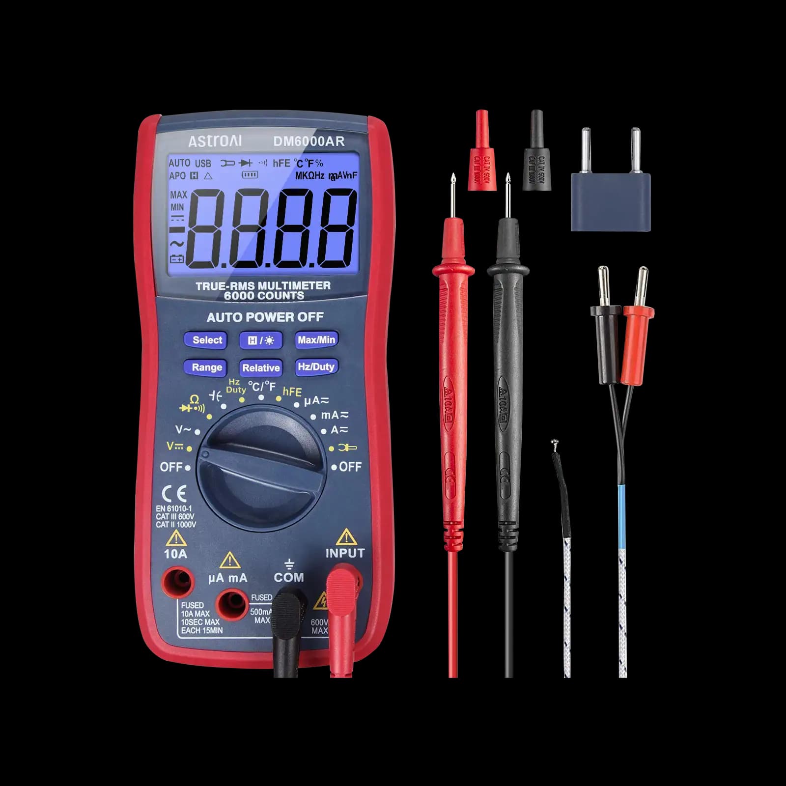
True RMS, 6,000-count, auto and manual ranging. No CAT rating stated, so it suits low-voltage boards.

22,000-count with 0.01 µA and 0.01 Ω resolution, REL mode and a USB PC link. Burden voltage not published.

True RMS with a 19,999-count high-resolution mode and an analog bar graph for changing readings. Hands-on Tested.
As an Amazon Associate I earn from qualifying purchases. Prices and availability are shown on Amazon.
Frequently asked questions
How much extra current is too much?
There is no universal threshold. Compare the reading with your own budget built from datasheet figures. A reading 10 to 30% above the estimate may only mean parts are drawing nearer their maximum figures, while a reading several times higher, one pinned at the supply's current limit, or one that keeps rising as the board warms points to a real fault that needs finding.
Why does my circuit draw too much current only after it warms up?
Leakage in semiconductors and some capacitors increases with temperature, and a marginal part can tip into failure once warm. A regulator running near its thermal limit or an oscillation that appears as parts heat can also do it. Log the current over time with a meter's Min/Max mode and use the heat-finding methods on the suspect area once the rise begins.
Can I find a short with the power off?
Often, yes. Measuring resistance between the supply rail and ground with the circuit unpowered shows whether a hard short exists, and low-ohm readings across different parts of the board can help locate it. Large capacitors on the rail read low briefly while they charge from the meter, so let the reading settle and test with the probes both ways round.
Will a current-limited supply protect every component?
It limits damage but doesn't guarantee safety. A small part directly across the rail can still overheat at currents the limit allows, since 1 A through a 1 Ω fault is still 1 W. Output capacitors on the supply can also deliver a brief surge before the limit takes over. Start with a low limit, connect before switching on, and raise it in small steps.
Why does my multimeter blow its fuse when I measure current?
On the amps or milliamps jack the meter is a near short circuit, so placing it across a supply, rather than in series, drives a large current through the fuse. A fault current above the range rating does the same. Start on the highest current range, break the circuit so the meter sits in series, and only then switch down to the mA range.
What does it mean when my bench supply shows CC?
CC means constant current: the load is trying to draw more than the current limit you set, so the supply holds the current at that limit and lets the voltage fall. On a working circuit it means the limit is set too low. On a faulty board that should draw far less, it confirms excess current, and the collapsed voltage tells you roughly how hard the short is.


