HOW-TO GUIDE
How to Test a Relay With a Multimeter: Coil, Contacts, and Common Failures
By the OhmSavvy Research Team ·

Unplug before you probe
Which kind of relay you have
The test method depends on what is inside the case. Most relays you'll meet fall into one of four groups:
Board-mount signal or power relay
Sealed plastic cube soldered to a PCB. One coil, one or two sets of changeover contacts.
Plug-in panel relay
Sits in a socket on a DIN rail or chassis, so it can be pulled and tested on its own.
Latching relay
Holds its last position with no coil current. Uses two coils, or one coil driven in either polarity.
Solid-state relay (SSR)
No coil and no moving contacts. An LED input drives a semiconductor output switch.
The numbered steps below apply to the first three groups. Solid-state relays need a powered test, covered further down. Car relays follow the same logic with their own pin numbering, covered in the automotive relay guide.
Finding the coil and contact pins
Every electromechanical relay has two coil pins and at least one contact set. In a changeover (SPDT) set, the common pin (COM) connects to the normally closed pin (NC) at rest and swaps to the normally open pin (NO) when the coil pulls in. A DPDT relay simply has two of these sets driven by the same coil.
Most relays print a small pin diagram on the case, often with the coil voltage. If yours doesn't, look up the part number on the maker's datasheet rather than guessing: on board-mount relays the coil pins and contact pins are not in the same place from one maker to the next. The whole test runs in the order below, and each stage only makes sense once the one before it has passed.
01
Identify pins
Case diagram or datasheet
02
Coil ohms
Compare with V² ÷ P
03
Contacts at rest
COM–NC closed, COM–NO open
04
Energize
COM–NO closed, COM–NC open
05
Under load
Volts across closed contacts
Symptoms, causes and fixes
Use this table to jump straight to the test that matches what the equipment is doing. The steps after it explain each measurement and the numbers to expect.
| Symptom | Likely cause | How to check | Fix or who to call |
|---|---|---|---|
| No click, load never switches | Open coil | Coil ohms: reads OL | Replace the relay |
| No click, coil ohms look fine | No drive signal or failed driver transistor | DC volts across the coil while commanded on: near 0 V | Repair the driver stage; board repair shop if unsure |
| Driver runs hot or relay chatters | Shorted coil turns | Coil ohms far below the datasheet or V² ÷ P figure | Replace the relay; check the driver too |
| Load stays on when it should be off | Contacts welded shut | COM–NO near 0 Ω with the coil off | Replace the relay; fit one rated for the load's inrush |
| Clicks, load won't run or flickers | Burned or pitted contacts | COM–NO with coil on: high, unstable, or large volt drop under load | Replace the relay |
| Works on the bench, fails in the unit | Low coil voltage or a poor socket or solder joint | Coil volts in circuit vs the must-operate voltage; inspect joints | Fix the supply, reflow joints or replace the socket |
1Measure the coil
With the relay out of circuit, or the board unpowered and the coil isolated, set the meter to resistance and probe the two coil pins. Compare the reading with the datasheet figure. If you only know the coil voltage and power, the rated voltage squared divided by the power gives a close estimate, because P = V² ÷ R rearranges to R = V² ÷ P. OL means the coil winding is open and the relay can never pull in. A reading far below the expected value suggests shorted turns, which can overload whatever drives the coil.
Worked example: a 12 V coil rated 0.36 W gives 12² ÷ 0.36 = 144 ÷ 0.36 = 400 Ω. The coil then draws 12 ÷ 400 = 30 mA when energized, which is the figure the driver transistor has to handle. Coil power around 0.36 to 0.45 W is common for small board-mount power relays, but check the datasheet for your part. The chart shows how the expected resistance climbs with coil voltage at the same 0.36 W.
Coil resistance is usually quoted at room temperature, around 20 to 23°C. Copper's resistance rises roughly 0.4% per degree Celsius, so a coil you measure straight after the equipment has been running warm, say 20°C hotter, reads about 8% high. That is normal and not a fault. If the relay has an internal suppression diode, a reversed probe pair may read low because the diode conducts. Swap the probes and use the higher reading, or check the diode separately with the diode test mode.
2Check the contacts at rest
Switch to continuity. With no power on the coil, COM to NC should beep and read close to zero ohms, and COM to NO should read OL. On a normally open relay with no NC pin, only the second check applies. Continuity from COM to NO at rest means the contacts have welded together, a common end of life for relays that switched inrush-heavy loads such as motors, transformers or lamps. A welded relay is the usual reason a heater, pump or fan refuses to switch off, and it should be replaced with one whose contact rating covers the load's start-up surge, not just its running current.
3Energize the coil and recheck
Apply the rated coil voltage from a bench supply or a battery of the right voltage, respecting any polarity marking. You should hear a click. Now COM to NO should read close to zero and COM to NC should read OL. Remove the coil voltage and both should swap back. Use your meter's relative (REL) mode to zero out the lead resistance before judging small values: test leads alone typically add a few tenths of an ohm, which is more than a good contact.
Many relay datasheets specify a must-operate (pick-up) voltage, often no more than about 75% of the rated coil voltage, and a must-release voltage, often at least 10%. For a 12 V coil that means it should pull in by 12 × 0.75 = 9 V and drop out once the voltage falls below about 1.2 V. If you have an adjustable supply, raising the voltage slowly and noting the click tells you whether a relay that works on the bench will also work in equipment whose supply sags.
If the relay clicks but COM to NO reads more than a fraction of an ohm, or the reading jumps around as you tap the case, the contact surfaces are worn. Small power relays commonly list an initial contact resistance of no more than about 100 mΩ, measured by the maker at a stated test current; a meter's low test current can read a little higher on a contact with a thin oxide film. For the careful version of this measurement, see how to measure relay contact resistance.
4Test the contacts under load, in circuit
A soldered relay can still be checked in place, with the circuit powered. First measure DC volts across the coil pins while the controller is commanding the relay on. Close to the rated coil voltage means the drive side works, so look at the relay. Near zero means the fault is upstream: often the driver transistor, which you can check with the in-circuit transistor test.
Then measure the voltage across the closed contacts while the load is running. This is the most revealing test of all, because it measures the contact at its real working current. Ohm's law does the rest. A contact at the 100 mΩ datasheet limit carrying 5 A drops 5 × 0.1 = 0.5 V and dissipates 5² × 0.1 = 2.5 W. A burned contact at 1 Ω carrying the same 5 A drops 5 V and turns 25 W into heat inside a small plastic case, which is how relays melt and why a worn contact gets worse quickly once it starts.
| Contact resistance | Volt drop at 5 A | Heat at 5 A |
|---|---|---|
| 0.05 Ω (good) | 0.25 V | 1.25 W |
| 0.1 Ω (typical datasheet limit) | 0.5 V | 2.5 W |
| 1 Ω (burned) | 5 V | 25 W |
On a mains circuit the same rule holds: a few volts across a closed contact is a failing relay, even if the load still runs. Only take that measurement if you are trained and equipped for live mains work.
A click is not a pass
Latching and solid-state relays
A latching relay stays in its last position after the coil is released, so step 2 may find the contacts in either state. Dual-coil types have a set coil and a reset coil: measure each coil separately, pulse one, check the contacts, then pulse the other and check again. A single-coil latching relay switches when you reverse the polarity of the pulse.
A solid-state relay has an LED on the input, much like an optocoupler, and a semiconductor output. Test it powered: connect a load such as a lamp on the output side, apply the rated control voltage, and measure the voltage across the load. It should rise to nearly the full supply when the input is on and fall when it is off. AC-output SSRs pass a small leakage current when off, so a high-impedance meter across an open output can still show a voltage. That is normal and does not mean the SSR has failed.
Meters for relay testing
Coil checks work on any meter. Contact checks are where meters differ: you want fine resolution on the lowest ohms range and a REL mode to subtract the leads, and a proper CAT rating if you will test relays in powered mains equipment. These picks come from our verified multimeter list.
Meters for coil and contact checks
True RMS, CAT III 600V, 6,000-count backlit display, with capacitance and frequency. Hands-on Tested.

22,000-count, 220.00 Ω range at 0.01 Ω resolution, and REL mode to zero lead resistance.
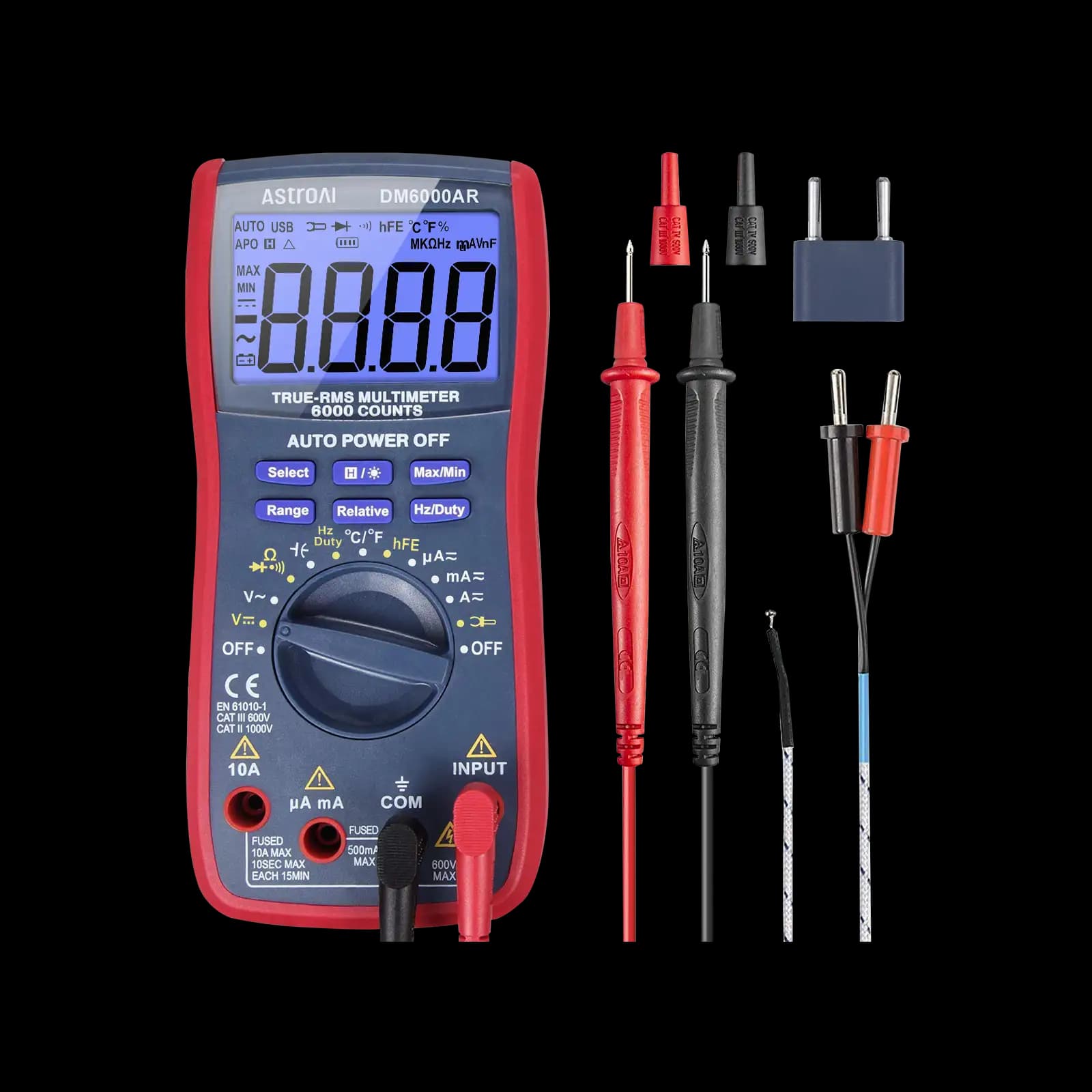
Budget True RMS, 6,000-count, auto and manual ranging. No CAT rating stated: low-voltage work only.
As an Amazon Associate I earn from qualifying purchases. Prices and availability are shown on Amazon.
Frequently asked questions
My relay clicks but the load still doesn't switch. Is the relay bad?
Often, yes. The click only proves the coil pulled the armature in. Pitted or burned contacts can move and still fail to make a low-resistance connection. Measure across the closed contacts with the coil energized, or measure the voltage dropped across them under load. On a low-voltage circuit, anything more than a small fraction of a volt points to worn contacts and a relay to replace.
Does it matter which way round I connect the coil supply?
For a plain coil, no. Many board-mount relays have a suppression diode built in, though, and some latching types are polarized. If the case shows a diode symbol or marks the coil pins with + and -, connect the supply that way round. Reversed, the internal diode conducts and the relay won't operate, and a small supply may be overloaded by the short.
What coil resistance should I expect?
The datasheet lists it, usually alongside the coil voltage and power, often with a tolerance of around ±10%. You can also estimate it: resistance is roughly the rated voltage squared divided by the coil power. A 12 V coil rated 0.36 W works out to 144 ÷ 0.36 = 400 ohms. OL means an open coil; a reading far below the estimate suggests shorted turns.
Can I test a solid-state relay with the ohms range?
Not meaningfully. An SSR has no coil and no metal contacts, just an LED on the input and a semiconductor switch on the output. Resistance readings across the output depend on the meter's test voltage and say little about whether it will switch a real load. Test it powered instead, with its rated control voltage applied and a load such as a lamp connected.
How do I test a relay without a datasheet?
Read the coil voltage printed on the case, then find the two pins that show a steady resistance between them: those are the coil. Of the remaining pins, the pair that reads near zero ohms at rest is COM and NC. Energize the coil at its printed voltage and find which pin then connects to COM: that is NO. Confirm the pinout before soldering a replacement.
What is a good contact resistance for a relay?
Small power relays commonly specify an initial contact resistance of no more than about 100 milliohms, measured by the maker at a stated current. Your meter's leads add a few tenths of an ohm, so zero them with REL mode first. A closed contact that reads well over the datasheet figure after zeroing, or jumps around when you tap the case, is worn.


