HOW-TO GUIDE
How to Test a Battery Protection Circuit With a Multimeter
By the OhmSavvy Research Team ·
Lithium cells can short, overheat and catch fire
B+, B−, P+ and P−
On a typical single-cell protection module (often called a PCM, or a BMS on larger packs) the positive is a straight-through connection: B+ and P+ are the same copper. The protection happens on the negative side, where a pair of MOSFETs sits between B− (the cell) and P− (the pack terminal). A small IC watches cell voltage and current and turns those MOSFETs off when something goes wrong.
B+ / B−
Pads soldered to the cell or cell stack. Always show the real cell voltage.
P+ / P−
Pack output, where the charger and load connect.
Dual MOSFET
Back-to-back switches in the negative path: one blocks discharge, one blocks charge.
Protection IC
Monitors voltage and current, drives both MOSFET gates.
1Measure cell voltage vs pack voltage
Set the meter to DC volts. Measure P+ to P− at the pack terminals first. Then open the pack enough to reach the board and measure B+ to B− directly across the cell pads. On a healthy, untripped board the two readings match to within a few millivolts with no load connected. A fully charged single cell typically reads around 4.2V and a flat one somewhere in the low 3V range; your cell datasheet has the exact limits.
| Measure | Healthy board | Tripped board | Dead cell |
|---|---|---|---|
| B+ to B− | Cell voltage, e.g. 3.7 V | Cell voltage, e.g. 2.9 V | Very low or 0 V |
| P+ to P− | Same as B+ to B− | 0 V or a few hundred mV | 0 V |
| B− to P− | A few mV or less | Close to cell voltage | 0 V |
2Recognize a tripped board
If B+ to B− shows a respectable cell voltage but P+ to P− reads zero, the board has opened the negative path. A quick confirmation is to measure from B− to P−: with the MOSFETs off, the cell voltage appears across them. Some boards leave a floating few hundred millivolts at the output instead of a clean zero because of leakage through the body diode and the meter's input, which means the same thing.
The common triggers are over-discharge (the cell sank below the IC's cut-off), over-current or a short on the output, and, less often, over-charge. Over-current trips usually reset once the load is removed. Over-discharge lockout usually stays latched until a charger is connected.
3Wake it with a charger
Disconnect any load and connect a charger designed for the pack's chemistry and cell count to P+ and P−. Most protection ICs release the over-discharge lock as soon as they see charge voltage, and the charge MOSFET's body diode lets a small current in even while the board is off. After a minute or so, disconnect the charger and measure P+ to P− again. If it now matches B+ to B−, the board was simply doing its job.
Don't jump the board with a bench supply
4Check the protection MOSFETs
With the board connected and not tripped, measure B− to P− while the pack drives a modest load. The drop across healthy MOSFETs is small, usually tens of millivolts at moderate current. A drop that grows to hundreds of millivolts, or a board that gets noticeably warm, points to damaged or partly switched MOSFETs.
For a definite test, desolder the board from the cells first. In diode mode, B− to P− should read OL in both directions, because the two body diodes face opposite ways and block each other. A reading near zero, or a beep, in both directions means at least one MOSFET has failed shorted, and the pack was running without protection. Most boards use a dual MOSFET in one package with a shared drain; probing from the common drain pad to each source pad shows each body diode separately, a forward drop one way and OL the other. Our MOSFET testing guide covers the single-device method in more detail.
5Measure balance taps on multi-cell packs
On 2S, 3S, 4S and larger packs the board has extra wires to each junction between cells, usually labeled B0 (or B−), B1, B2 and so on up to B+. Measure each adjacent pair, B0 to B1, B1 to B2, and so on, to read each cell group on its own. The individual readings should add up to the total across the stack and should sit close together on a balanced pack; a spread of more than about a tenth of a volt is commonly treated as a warning sign.
One weak group is a classic cause of a pack that "dies" early: the board trips on the lowest cell even though the total looks healthy. A tap that reads 0V while the total is normal can also mean a broken balance wire rather than a dead cell, so check continuity of that wire before condemning anything. A weak group can also look fine at rest and sag under load, the same effect our car battery guide uses to separate a tired battery from a healthy one.
Reading the results
| What you measure | Likely cause |
|---|---|
| P+/P− matches B+/B−, small drop under load | Board and cell healthy |
| B+/B− normal, P+/P− near 0 V, recovers on charger | Over-discharge or over-current trip; board working |
| B+/B− above cut-off, P+/P− stays 0 V on a charger | Failed IC or MOSFET stuck off; replace board |
| B−/P− shorted both ways in diode mode, board off | MOSFET failed shorted; pack has no protection |
| Large B−/P− drop under load, board warm | Damaged MOSFETs or under-rated board for the load |
| B+/B− very low or 0 V | Cell deeply discharged or dead; treat with caution |
| One balance group much lower than the rest | Weak or self-discharging cell group |
Meters for battery and protection board work
Protection board checks are mostly DC volts read to two decimal places, plus diode mode across the MOSFETs. A 6,000-count meter resolves a single lithium cell to 0.001 V on its 6 V range, which is enough to compare a cell with its pack terminals or spot a weak balance group. Fine probe tips matter as much as the meter, because the B and P pads sit close together. For larger packs, see checking cell imbalance in a 48V LiFePO4 pack.
Meters for pack and BMS checks
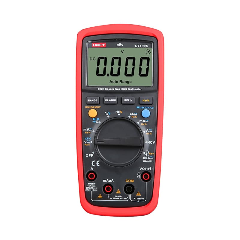
Affordable 6,000-count meter, CAT III 600V, with auto or manual ranging for cell and balance-tap readings.

Hands-on tested. Backlit 6,000-count display and robust Fluke build for regular battery pack repair.
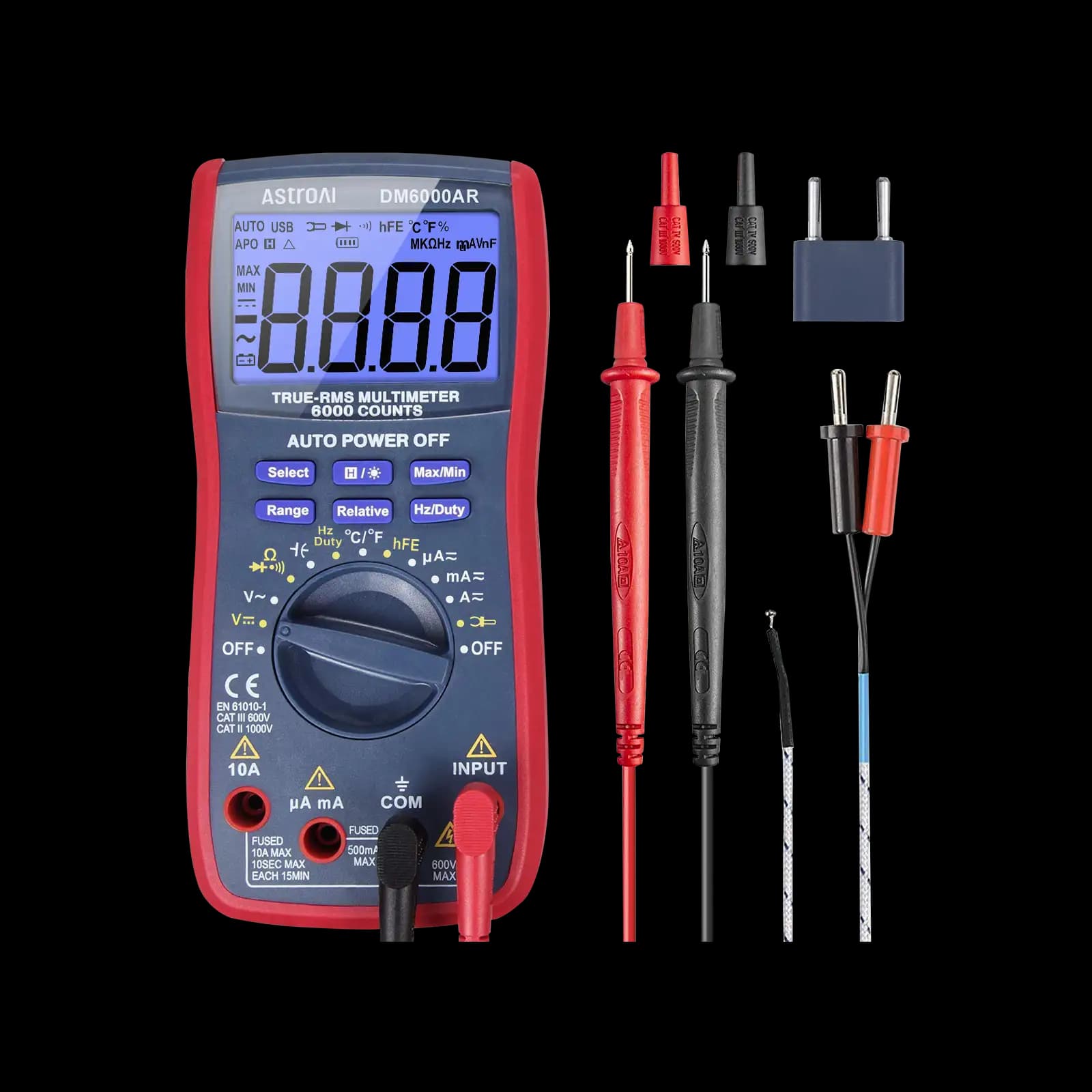
Inexpensive 6,000-count meter for hobby packs; AstroAI states no CAT rating, so keep it off mains.
As an Amazon Associate I earn from qualifying purchases. Prices and availability are shown on Amazon.
Frequently asked questions
Why does my lithium battery read 0V but the cell inside reads 3V?
The protection board has switched its MOSFETs off, usually after an over-discharge or over-current event, so the pack terminals are disconnected from the cell. B+ to B− shows the cell voltage while P+ to P− shows zero or a small floating value. Connecting a proper charger normally releases it if the cell is above the board's release threshold.
At what voltage does a protection board cut off?
It depends on the protection IC and the pack design. Single-cell boards commonly cut off somewhere around 2.4 to 3.0V per cell on discharge and around 4.25 to 4.35V on charge, with a separate over-current and short-circuit limit. Check the IC's datasheet or the pack's specification for the actual figures.
Is it safe to bypass a protection board by bridging B− to P−?
No. Bridging the board removes over-discharge, over-charge and short-circuit protection at once, and a shorted lithium cell can deliver very high current. If the board needs waking, use a charger with its own current limit. If it has failed, replace the board with one matched to the cell count and current.
Can a protection board fail and leave the pack unprotected?
Yes. A MOSFET can fail shorted, which leaves the output permanently connected. The pack still works normally, so nothing seems wrong until the cell is over-discharged or shorted. A diode-mode check across the MOSFETs on a board removed from the cells reveals it.
Should I try to revive a cell that reads very low?
Be cautious. A lithium-ion cell that has sat well below its minimum voltage, commonly cited as below about 2V, may have internal damage that makes recharging unsafe. Many manufacturers advise recycling such cells. A cell that has only just dropped below the cut-off is a different case and usually recovers on a normal charger.


