HOW-TO GUIDE
How to Measure Resistance Across a Relay Contact With a Multimeter
By the OhmSavvy Research Team ·

Before you start
- Ohms tests are made with the circuit dead. Remove the relay, or switch off and isolate the circuit and disconnect the contact terminals before measuring resistance.
- Relays often switch mains voltage. Do not make live voltage-drop measurements on mains contacts unless you are competent to work near live terminals with a meter and leads rated for the circuit. The worked examples here are low-voltage DC.
- Energise the coil only at its rated voltage, from a fused bench supply or battery, not from the meter. A coil produces a voltage spike when it is switched off, so keep your fingers off its terminals.
COM, NO and NC: know which contact you are testing
Most relays show their contact arrangement on the case or in the datasheet. General-purpose and PCB relays use COM, NO and NC; automotive relays use 30, 87 and 87a for the same jobs, as covered in our guide to testing an automotive relay. Relays with several poles repeat the set for each pole, and each one is tested separately.
COM (common)
The moving contact. Every measurement is made from here.
NO (normally open)
Connects to COM only while the coil is energised.
NC (normally closed)
Connects to COM while the coil is off; opens when it is energised.
1Null the test leads
Select the lowest resistance range, not continuity: the continuity beeper on many meters sounds at tens of ohms and cannot tell a good contact from a poor one. Press the probe tips firmly together. The display shows the resistance of the leads, tips and sockets, often a few tenths of an ohm. Press REL (or Δ) to subtract it, or note it and subtract it yourself. The method is explained in our guide to measuring resistance in ohms.
2Measure the contacts with the coil off
With no power on the coil, measure COM to NC: it should read the same as the shorted leads, about 0.0 after REL. Then measure COM to NO: it should read OL. Tap the relay gently while watching the NC reading. A value that flickers or jumps means the contact is not seating firmly.
3Energise the coil and measure NO
Find the coil voltage on the case or datasheet: 5 V, 12 V and 24 V DC coils are common, and AC coils exist for mains control. Apply that voltage from a suitable supply, observing polarity if the coil has a built-in suppression diode or the relay is marked with + and −. You should hear it click.
With the coil held energised, COM to NO should now match the shorted leads and COM to NC should read OL. Switch the coil on and off ten or so times and measure after each closure. A good contact gives the same reading every time; a worn one gives a different value on each operation.
If the relay does not click at all, the contacts are not the problem yet. Measure the coil resistance across its terminals with the supply disconnected and compare it with the datasheet; an OL reading means an open coil. Also confirm your supply really delivers the rated voltage at the coil while it is connected, since a weak battery or long thin leads can leave too little to pull the armature in.
Why an ohms reading cannot show milliohms
Relay datasheets usually give a maximum contact resistance in milliohms, measured with a specified test current. On a typical handheld meter, the lowest range resolves 0.1 Ω or 0.01 Ω, and lead contact pressure alone can shift a reading by a count or two. So a contact of 20 mΩ and one of 80 mΩ can both display 0.0 after REL, even though one is four times worse than the other.
The test current also matters. An ohmmeter passes only a small current, while the relay's job may be to carry several amps. A contact with a pitted surface can touch on a tiny spot that passes the meter's current without trouble and then overheats at load current. Benchtop low-resistance ohmmeters avoid both problems with a four-wire connection and a higher test current, but the voltage-drop method below gets you most of the way with an ordinary multimeter.
The opposite case exists too. Relays meant for tiny signal currents often use gold-plated contacts, while power relays use contact materials that rely on a minimum current to keep their surfaces clean. Datasheets often list a minimum switching load for this reason. A power relay used for years on a very small signal can develop a film that gives an erratic reading at low current, even though the contact has never carried much load.
The voltage-drop method under load
Leave the relay in its working circuit, or wire it to a test load of known current, and switch the load on. Set the meter to DC millivolts and put the probes directly on the COM and NO terminals, not on the wires further away. The reading is the voltage lost across the closed contact. Measure the load current with a clamp meter, or in series with the meter on its amps range, and then divide: resistance R = V ÷ I. The heat generated in the contact is P = V × I.
| Example | Load current | Drop across contact | R = V ÷ I | Heat P = V × I |
|---|---|---|---|---|
| Small signal relay, good | 0.5 A | 20 mV | 40 mΩ | 0.01 W |
| Automotive relay, good | 10 A | 50 mV | 5 mΩ | 0.5 W |
| Same relay, pitted | 10 A | 400 mV | 40 mΩ | 4 W |
| Power relay, badly burnt | 20 A | 1.2 V | 60 mΩ | 24 W |
These figures are illustrative. Notice that the small signal relay and the pitted automotive relay have the same 40 mΩ, yet one dissipates 0.01 W and the other 4 W: contact resistance only matters in relation to the current it carries. The yardsticks are the relay datasheet and an identical relay known to be good, measured at the same current.
A few practical points make the reading trustworthy. Probe the relay's own terminals or the socket pins right beside them; every connector and length of wire you include adds its own drop. Let the load run for a minute or two, because a poor contact warms up and its drop often climbs. On a multi-pole relay, measure every pole that carries current and compare them. Keep the probe tips from bridging neighboring pins, which on a car relay could short a powered circuit.
Bars use a logarithmic scale: each step is ten times the last.
The same idea, applied to whole wiring runs and grounds rather than one contact, is in our guide to checking voltage drop on a car.
Pitted, burnt and welded contacts
Every time a contact opens or closes under load, a small arc erodes its surface. Over many operations the surface becomes pitted and blackened, the voltage drop rises and the contact runs hotter, which accelerates the wear. Symptoms are a load that works intermittently, a relay that feels hot, or a voltage drop that changes from one operation to the next.
A welded contact is the opposite failure: high inrush current, such as from a motor, lamp or capacitive power supply, fuses the contacts together. With the coil off, COM to NO reads close to zero and COM to NC reads OL, so the load stays on regardless of the control signal. Replace the relay, and check whether its contact rating suits the load's inrush, or the replacement will fail the same way.
Reading the results
| What you measure | What it means |
|---|---|
| Closed contact matches the shorted leads; open contact reads OL | Contacts switch correctly; check the drop under load if in doubt |
| Closed contact reads tenths of an ohm or more above the leads | Contact surface is badly degraded; replace the relay |
| Reading changes on every operation | Worn or pitted contact |
| COM–NO near 0 Ω with the coil off | Welded contact |
| Coil clicks but COM–NO stays OL | Burnt-open contact or broken internal connection |
| Voltage drop far above an identical good relay at the same current | High contact resistance; the contact will run hot |
The click proves the coil, not the contact
Which meter to use
For contact checks, the useful features are a low resistance range with REL, a DC millivolt range with good resolution, and a CAT rating that suits the circuits you work on. Check your manual for the resolution of the lowest ohms and millivolt ranges. These meters are from our best multimeters roundup.
Meters in our reviews
True RMS, CAT III 1000V / CAT IV 600V. The step-up pick for CAT IV protection and high-resolution readings.
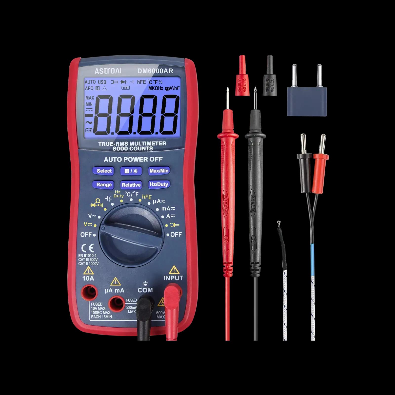
True RMS, 6,000-count, auto-ranging. Our pick for microcontroller and electronics projects.
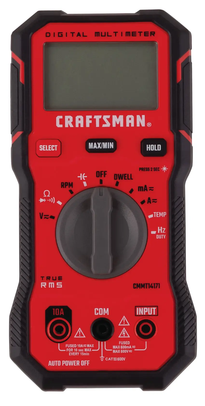
True RMS, auto-ranging, CAT III 600V. The pick built specifically for diagnosing cars.
As an Amazon Associate I earn from qualifying purchases. Prices and availability are shown on Amazon.
Frequently asked questions
What is a good contact resistance for a relay?
Relay datasheets usually state a maximum initial contact resistance, commonly in the tens of milliohms to around 100 milliohms for small relays, measured under defined test conditions. Use that figure for your part. In practice, compare the voltage drop at load current with a known-good identical relay; a contact several times higher than its twin is wearing out.
Why does my relay contact read 0.0 ohms but the load still does not work?
An ohms test uses a tiny current, and a pitted contact touching on one small spot can pass it easily yet heat up or drop volts at full load current. The fault may also be elsewhere: the coil drive, a connector or the load. Measure the voltage across the contact while the load is switched on to find out.
Can I clean pitted relay contacts?
On sealed PCB and automotive relays you cannot reach the contacts, so replacement is the only option. Open industrial contactors sometimes have replaceable contact kits, and their manufacturers give guidance on whether dressing is allowed. Filing contacts that are not designed for it removes the contact plating and usually shortens their life, so replacing the relay is the normal fix.
Do I need to remove the relay to test its contacts?
For an ohms test, yes, or at least disconnect the contact terminals, because other parts of the circuit connected across the contacts can give a false reading. The voltage-drop test is the exception: it is done with the relay in its working circuit, with power on and the load running, so the contact is tested under real conditions.
Can I test a solid-state relay the same way as a mechanical one?
No. A solid-state relay switches with a semiconductor such as a triac or MOSFET rather than metal contacts, so an ohms reading across its output tells you little and may show leakage or nothing at all. Many AC types also need load current flowing before they switch properly. Apply the control voltage from the datasheet to the input, then check the output in circuit with a real load connected.


