HOW-TO GUIDE
How to Measure Voltage Across a Resistor
By the OhmSavvy Research Team ·

Why voltage measurement doesn't need isolation
Voltage is inherently a measurement between two points, not a property of one isolated component — and a multimeter's voltage input is built with very high internal resistance, so almost no current flows through the meter itself during the measurement. That means connecting the probes across a resistor, even one sitting among other parallel components, doesn't meaningfully change the circuit's behavior. This is the opposite situation from resistance measurement in a parallel circuit, where the meter's own test current does flow through every available path.
1Set the meter to volts
Set the dial to DC voltage (or AC voltage for an AC circuit) on a range comfortably above what you expect to read, or use auto-ranging if available. Confirm the red lead is in the V jack, not an amps jack; that one check prevents the most expensive mistake on this page.
2Note the resistor's value before you power up
Read the color bands or the printed code, or take it from the schematic. You'll need the resistance later to turn the voltage into a current, and knowing whether it's 47Ω or 4.7MΩ also tells you whether the meter's own loading will matter (see below).
3Probe both leads with the circuit powered
With the circuit powered, touch one probe to each lead of the resistor directly, not to other points further along the circuit, and read the display. On a crowded board, touch the resistor's solder pads rather than the traces leading away from them, so you know exactly which component you're reading across.
4Sanity-check the number
Compare it with what the circuit should do. A drop larger than the supply is impossible and means you're probing the wrong points; exactly 0V with power present means no current is flowing through that path; and a value that drifts may be a changing signal rather than a fault.
Probe polarity and what a negative reading means
On DC voltage, a negative reading simply means the probes are reversed relative to actual current flow direction — the red probe is on the less positive side. This doesn't damage the meter; it just means swapping the probes gives the same magnitude with a positive sign. Note which lead is more positive when it matters for your diagnosis.
Using the reading to calculate current
This measurement is genuinely useful beyond just confirming a voltage: once you know the voltage dropped across a resistor of known value, Ohm's law gives you the current flowing through it — without ever breaking the circuit open the way a direct in-series current measurement requires.
I = V / R
Worked example: three resistors in series
The same technique extends naturally to a chain of several resistors in series: measure across each one individually, and the drops should add up to the supply voltage across the whole chain.
| Resistor | Voltage drop | Share of total |
|---|---|---|
| 100Ω | 1.85V | 15% |
| 220Ω | 4.06V | 34% |
| 330Ω | 6.09V | 51% |
| Total (650Ω, 12V supply) | 1.85 + 4.06 + 6.09 = 12.00V | 100% |
Each resistor's share of the total voltage is proportional to its own resistance relative to the chain's combined resistance (650Ω here) — this is the voltage-divider relationship that series resistor chains follow, and it's the same current (12V ÷ 650Ω ≈ 18.5mA) flowing through all three, since they share one series path.
When the meter itself changes the reading
"Very high impedance" isn't infinite. Most digital multimeters present roughly 10MΩ on their DC volts range (check your meter's manual for its exact figure). When you probe across a resistor, that 10MΩ sits in parallel with it. Against a 1kΩ resistor the effect is far too small to see, but against resistors in the megohm range the meter steals a noticeable share of the current and the reading drops.
Worked example: two equal resistors divide 10V, so each should show 5V. With 1MΩ resistors, the meter's 10MΩ in parallel with the lower one makes about 0.909MΩ, and the reading becomes 10 × 0.909 / (1 + 0.909) ≈ 4.76V, almost 5% low. The chart repeats that arithmetic for other resistor values, assuming a 10MΩ meter.
Bars use a logarithmic scale: each step is ten times the last.
Bar length shows the reading error. If you're working on high-value parts such as sensor bias networks or a CMOS input's pull-up, expect the meter to read low and treat the number as a lower bound. Our voltage divider guide covers how to correct for it.
Common mistakes
| Mistake | Result |
|---|---|
| Measuring across the wrong two points | Reading reflects a different part of the circuit than intended |
| Using current mode instead of voltage mode | Risk of a short circuit through the meter and a blown fuse |
| Ignoring a 0V reading where current was expected | Missing an open circuit elsewhere in that current path |
| Reading a rapidly fluctuating signal as one static value | A changing or PWM signal is better suited to an oscilloscope |
Never use current mode across a component like this
Which meter to use
Every multimeter can read voltage across a resistor. Extra display counts help when you're comparing small drops, such as the millivolts across a current-sense resistor; see how to test a shunt resistor for that case.
Meters from our reviews
Hands-on tested. True RMS, auto-ranging, CAT III 600V.

Hands-on tested. 19,999-count high-resolution mode for small voltage drops.
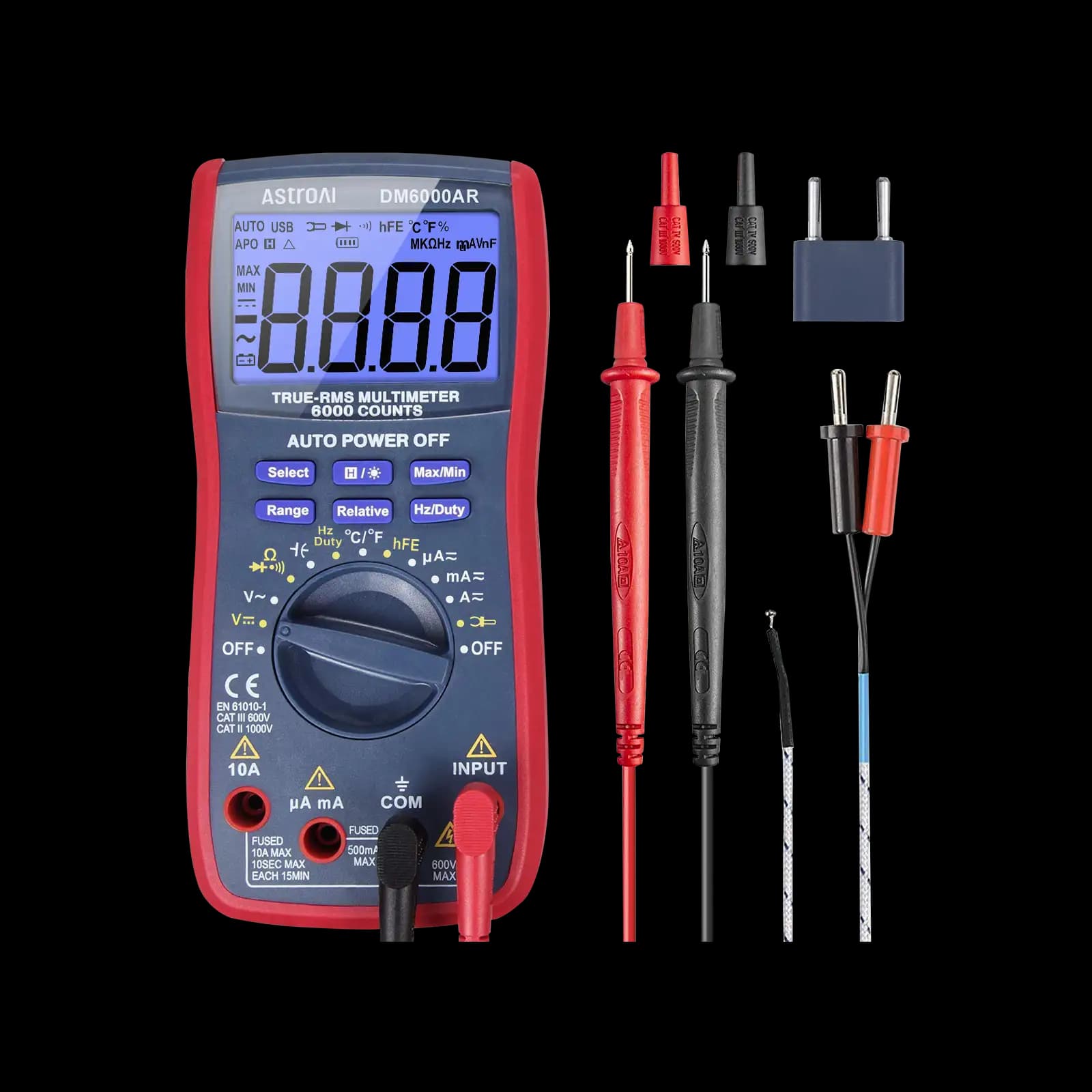
Budget 6,000-count True RMS for low-voltage electronics; no CAT rating stated.
As an Amazon Associate I earn from qualifying purchases. Prices and availability are shown on Amazon.
Frequently asked questions
Do I need to disconnect anything to measure voltage across a resistor?
No — this is the key difference from resistance measurement. A multimeter's voltage input has very high impedance, so touching the probes across a component while the circuit is powered doesn't meaningfully disturb the circuit or require isolating the resistor from anything in parallel with it.
What does it mean if I read 0V across a resistor that should have current flowing through it?
By Ohm's law (V = I × R), zero voltage across a resistor with a non-zero resistance means essentially zero current is flowing through it — which usually points to an open circuit somewhere else in that path, not a problem with the resistor itself.
Can I use this method on an AC circuit too?
Yes, as long as you switch the multimeter to AC voltage mode rather than DC. The same principle (Ohm's law relating voltage, current, and resistance) applies, though AC circuits with reactive components (capacitors, inductors) need additional care since voltage and current aren't always simply in phase.
Why does my reading fluctuate instead of settling on one number?
This usually reflects something genuinely changing in the circuit, such as a varying load, a PWM-controlled signal, or a loose connection at the resistor's leads — not an inaccurate meter. If the fluctuation is rapid and regular, it may actually be a signal you'd be better off viewing on an oscilloscope rather than reading as a single multimeter value.
Do the voltages across several resistors in series add up to anything useful?
Yes — in a series chain, the individual voltage drops across each resistor always add up to the total supply voltage across the whole chain. Measuring each drop and checking that they sum correctly is a quick way to confirm you haven't missed a component or misread one of the values.

