HOW-TO GUIDE
How to Test an Automotive Relay With a Multimeter
By the OhmSavvy Research Team ·
Remove the relay from its circuit before testing
Standard automotive relay pinout
Most automotive relays use a standard 5-pin layout, though some simpler relays use 4 pins (omitting the normally-closed contact). The numbers are usually molded into the relay case itself.
Pins 85 / 86
The coil. Polarity matters only if the relay has an internal protection diode.
Pin 30
Common — the input side of the switched contacts.
Pin 87
Normally open (NO) — connects to 30 once the coil is energized.
Pin 87a
Normally closed (NC) — connects to 30 at rest, disconnects when energized (5-pin relays only).
1Test coil resistance
Set the multimeter to resistance mode and measure across pins 85 and 86. A reading within the relay's typical range (check the datasheet or case marking) indicates a healthy coil winding. An open (OL) reading means the coil winding has failed — the relay won't energize no matter what controls it.
2Check the resting contact state
With the relay unpowered, set the multimeter to continuity mode. Pin 30 should show continuity with pin 87a (normally closed) and no continuity with pin 87 (normally open). This confirms the contacts are in their correct resting position before you energize anything.
3Energize the coil and recheck
Using a separate 12V source (not the multimeter), apply power to pins 85 and 86, observing correct polarity if the relay has an internal diode. You should hear an audible click. With the coil still energized, recheck continuity: pin 30 should now show continuity with pin 87 (normally open) and no longer show continuity with pin 87a.
The coil resistance tells you what current your 12V source has to supply. As a worked example, a coil measuring 80Ω draws 12 ÷ 80 = 0.15 A, or 150 mA, which any fused jumper lead or small bench supply handles easily. That same figure is a useful check on the circuit that drives the relay: a body control module or switch only has to sink about 150 mA, while the contacts it controls may carry 20 A or more to a fan or fuel pump.
4Voltage-drop test under load
Continuity mode only proves the contacts touch; it can't show that they pass full current. To check that, plug the relay back in (or use a relay test jumper), run the circuit, and set the meter to DC volts. Probe pin 30 and pin 87 while the load is on. A healthy contact set typically drops only a small fraction of a volt, often under about 0.2V. A reading of a volt or more with the load running points to pitted contacts that pass a continuity beep but starve the load. Treat these thresholds as rules of thumb and check the service manual where it gives a figure.
Interpreting the results
| Test result | Likely condition |
|---|---|
| Coil shows OL (open) | Failed coil winding — relay needs replacing |
| No continuity 30–87a at rest | Contacts stuck open, or wrong pins identified — recheck the pinout |
| No click when energized, coil resistance is normal | Mechanical fault in the armature, or a wiring/polarity issue on the test leads |
| Clicks, but no continuity 30–87 when energized | Contacts pitted, burnt, or welded in the wrong position — relay needs replacing |
A clicking relay isn't automatically a working relay
Mini, micro, and standard relay sizes
The 5-pin layout and testing process above apply regardless of physical size — automotive relays mainly come in three common form factors, distinguished by case size and current rating rather than by how their pins function.
Standard (ISO) relay
The common full-size automotive relay body, typically rated well above 20A on the switched contacts.
Mini relay
A smaller case for the same basic function, common in modern vehicle fuse/relay boxes.
Micro relay
Smaller still, often used where panel space is tight; typically a lower current rating than mini or standard.
Typical coil resistance by relay type
These are commonly cited ranges, not a substitute for checking the specific relay's own datasheet or case marking — individual parts vary by manufacturer even within the same category.
Meters for relay testing
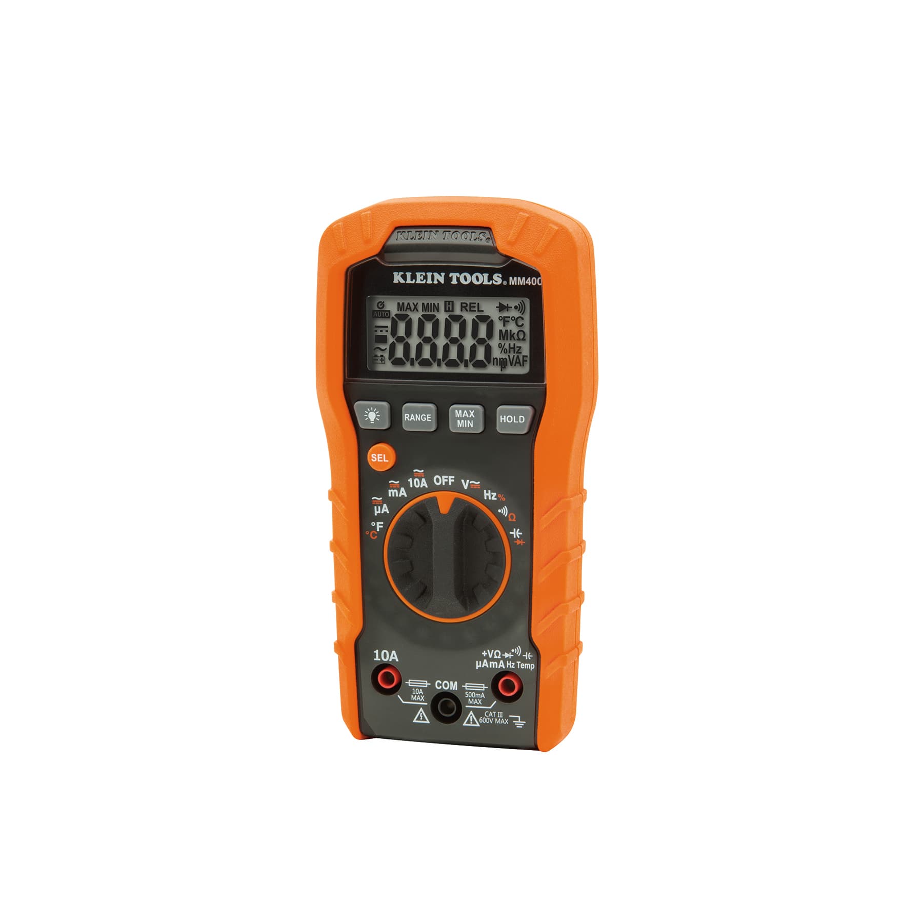
Any meter with resistance, continuity and DC volts covers the four steps above. For regular automotive work, a fast continuity beeper, Min/Max capture for intermittent faults and automotive extras make the job quicker. These picks from our automotive coverage fit that brief.
Meters for relay and circuit checks
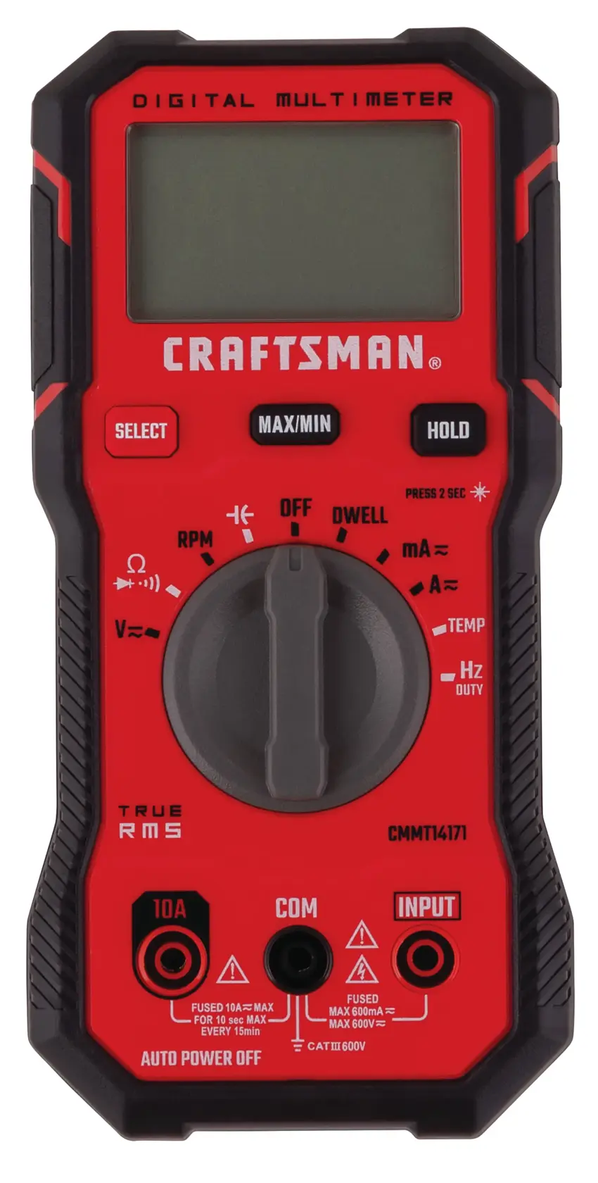
True RMS, CAT III 600V, with RPM, dwell and duty cycle for the wider diagnosis around a relay fault.
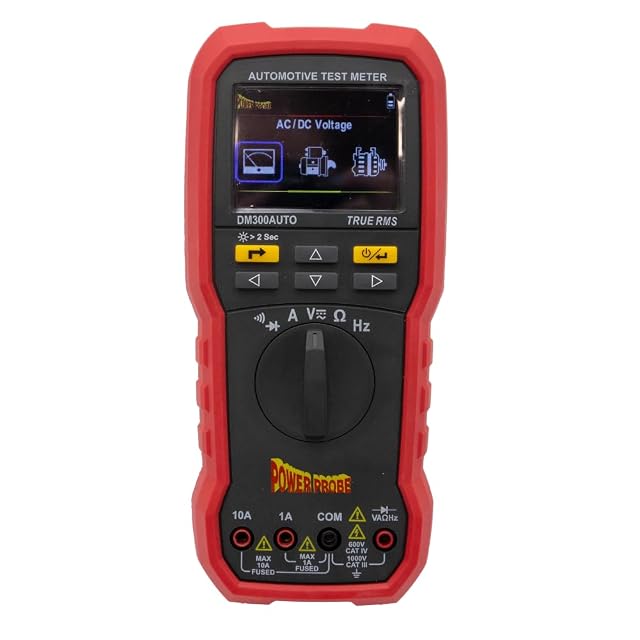
Fuse-current mode estimates the current a relayed circuit draws through its fuse, up to 80 A, without pulling the fuse.

Budget 6,000-count True RMS meter with Min/Max, handy for catching a relay that drops out intermittently.
As an Amazon Associate I earn from qualifying purchases. Prices and availability are shown on Amazon.
Frequently asked questions
What resistance should a healthy relay coil show?
It varies by relay — commonly somewhere in the tens to low hundreds of ohms for typical automotive relays, but this differs by part number and manufacturer. Check the relay's datasheet or the number printed on its case for the exact figure where precision matters; what's most diagnostic is an open (infinite) reading, which clearly indicates a failed coil regardless of the exact expected value.
Do I need a 12V source to fully test a relay, or can the multimeter power the coil?
You need a separate 12V source — a multimeter's own test current is far too small to energize a relay coil. A bench supply, a car battery with fused jumper leads, or a 12V battery pack all work, as long as you observe correct polarity on relays with an internal protection diode across the coil.
Why does my relay click but the circuit it controls still doesn't work?
An audible click confirms the coil is pulling the armature, but doesn't confirm the switch contacts themselves are making good electrical contact — pitted or burnt contacts can click mechanically while failing to pass current cleanly. Test continuity through the switched contacts while the coil is energized, not just listen for the click.
Can a relay fail intermittently and still pass a bench test?
Yes — intermittent faults (contacts that work when cold but fail when hot, or a coil with a marginal winding that fails under vibration) can pass a static bench test and still cause real-world problems. If symptoms point at a relay that tests fine, consider testing it again under load or after it's warmed up in its actual operating position.
Can I swap a relay with an identical one to test it?
Yes, and it's a quick first check: many fuse boxes use several relays with the same part number, such as horn and fog-light relays. Swap the suspect relay with a matching one from a non-critical circuit and see whether the fault moves. Only swap relays with identical part numbers and pin diagrams, because a diode-equipped relay or a changeover type may not behave the same.



