HOW-TO GUIDE
How to Measure the Resistance of a Speaker With a Multimeter
By the OhmSavvy Research Team ·

Amplifier off, speaker disconnected
- Switch the amplifier or head unit off before touching the speaker wires. A resistance range cannot measure a connected, powered load, and an amplifier output can damage the meter.
- Many amplifiers hold charge in large supply capacitors after switching off. Wait before working on terminals inside the amplifier itself, and keep to the speaker side of the wiring.
Speaker DC resistance vs nominal impedance
A speaker's rating of 4, 8 or 16 Ω is its nominal impedance, the opposition it presents to an AC audio signal. It changes with frequency and includes effects from the coil's inductance and the cone's motion. A multimeter instead passes a small direct current through the coil and reports the resistance of the copper or aluminum wire, often written as Re or DCR on spec sheets. That figure is always lower than the nominal rating.
1Disconnect the speaker
With the amplifier off, remove at least one wire from the speaker terminals. Left connected, the meter reads the driver in parallel with the amplifier's output stage and any other speakers on the same channel. In a car or home cabinet, getting at the driver's own tabs gives the clearest answer; measuring from the far end of the cable also includes the wire, which is useful for spotting a damaged run. The methods in testing electrical wires help separate a cable fault from a driver fault.
2Zero the test lead resistance
On low-ohm readings the probe leads matter. Select the lowest Ω range, press the probe tips firmly together and read the display. Typical leads read a few tenths of an ohm. Either subtract that from every speaker reading or, if your meter has a relative (REL or Δ) button, press it with the probes shorted so the display zeroes out the leads.
Why a few tenths matter
3Measure the voice coil
Hold one probe on each speaker terminal. Polarity does not matter for the reading. Let the display settle, then subtract the lead value. While the probes are on, press the cone gently in and out by a few millimeters: the reading should stay steady.
01
Amp off
Disconnect one wire
02
Lowest Ω
Short probes, note leads
03
Probe terminals
Subtract lead value
04
Flex the cone
Reading stays steady
05
Compare
≈ 75–90% of nominal
Open, shorted or good: reading the result
| Reading (after subtracting leads) | Likely condition |
|---|---|
| About 75–90% of the nominal rating, steady | Coil intact |
| OL | Open voice coil or broken lead-out wire; driver needs replacing or reconing |
| Near 0 Ω, or far below the typical band | Shorted turns from overheating, or a short in the wiring |
| Flickers as the cone moves | Fraying tinsel lead or a cracked joint at the terminal |
| Normal reading but distorted sound | Coil rubbing or a torn cone; not visible to a meter |
A blown speaker from overpowering often fails open, so OL is the most common bad result. Partial shorts are less frequent but show up as a reading well below the expected band, for example around 2 Ω on a driver marked 8 Ω.
Speakers with crossovers: why to disconnect
Multi-way speakers split the signal with a passive crossover. Tweeters are fed through a series capacitor, which blocks the meter's DC test current entirely, and woofers through an inductor that adds its own winding resistance. Measured at the cabinet's input, you mostly see the woofer plus its inductor, and nothing of the tweeter.
Tweeters typically read a little lower than their nominal rating, just like woofers. If the driver checks out and the tweeter is still silent, the crossover capacitor itself may have failed; our guide to testing a capacitor with a multimeter covers that next step.
Measuring speakers wired in series or parallel
When several drivers share one amplifier channel, measuring across the combination tells you the load the amplifier sees. Series connections add; parallel connections combine as in our guide to measuring resistance in a parallel circuit. Typical combined readings, using drivers that each read 6.5 Ω or 3.25 Ω DC:
| Wiring | Nominal load | Typical DC reading |
|---|---|---|
| Two 8 Ω in series | 16 Ω | ≈ 13 Ω |
| Two 8 Ω in parallel | 4 Ω | ≈ 3.3 Ω |
| Four 8 Ω, series-parallel | 8 Ω | ≈ 6.5 Ω |
| Two 4 Ω in parallel | 2 Ω | ≈ 1.6 Ω |
A combined reading that is too high usually means one driver in a parallel set is open; too low suggests a short or an unintended extra connection. Check that the final nominal load suits the amplifier's rated minimum impedance.
Which multimeter is good for speaker checks
You need a resistance range with 0.1 Ω resolution and a meter whose leads and jacks make solid contact. Most auto-ranging digital meters manage this. The specification that matters is low-ohm accuracy, explained in multimeter accuracy for electronics repair. New to the dial? Start with how to use a multimeter.
Meters for speaker coil checks
A voice coil reads only a few ohms, so the lead offset matters. These meters give clear low-ohm readings, and one can subtract the leads for you.
Meters for speaker resistance
A hands-on tested Fluke with a 6,000-count display, which typically means 0.1 Ω resolution on the lowest ohms range, enough for a 4 Ω or 8 Ω driver.
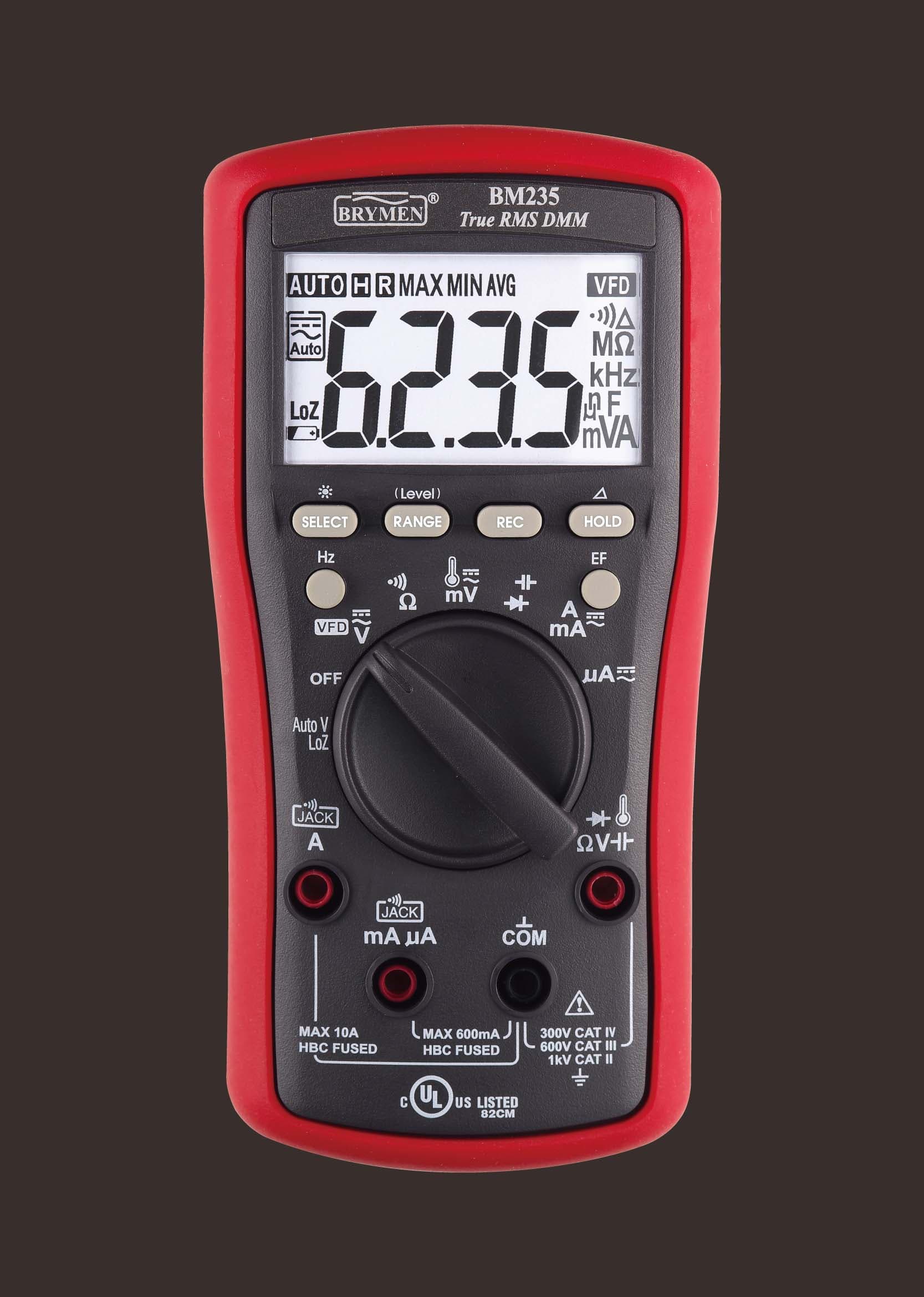
Relative zero lets you store the shorted-lead reading so the display shows only the coil's resistance.
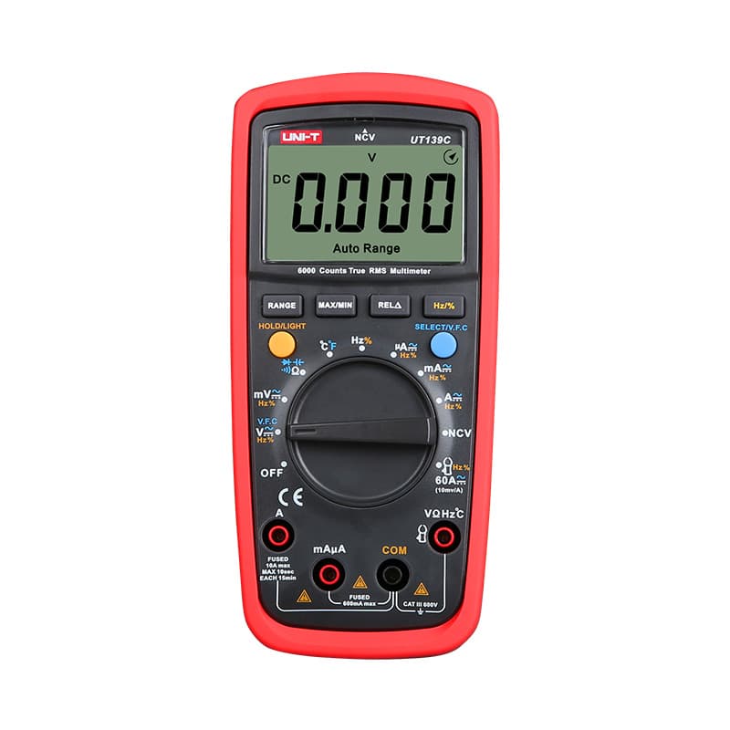
An affordable 6,000-count meter with manual ranging, so you can lock it on the lowest ohms range for a row of drivers.
As an Amazon Associate I earn from qualifying purchases. Prices and availability are shown on Amazon.
Frequently asked questions
Why does my 8 ohm speaker read 6 ohms?
Because the 8 Ω rating is nominal impedance, an AC figure that includes the voice coil's inductance and its motion in the magnet gap across the audio band. A multimeter measures only the DC resistance of the coil wire, which is typically around 75 to 90 percent of the nominal rating. A reading of about 6 to 7 Ω is normal for an 8 Ω driver.
Can I tell a speaker's impedance from its resistance?
Roughly. Measure the DC resistance and pick the nominal value just above it: around 3.2 Ω usually means a 4 Ω driver, around 6.5 Ω usually means 8 Ω, and around 13 Ω usually means 16 Ω. Treat this as a good guess for an unmarked driver, not a specification, and confirm with the label or datasheet when you can.
Will a multimeter damage my speaker?
No. A multimeter's resistance range drives only a small test current through the coil, far less than an amplifier delivers. On some woofers you may hear a faint click or see the cone twitch as the probes connect, which is harmless. Do make sure the amplifier is off and disconnected, both for the meter's sake and for an accurate reading.
Why does my speaker read OL through the crossover?
If you are measuring a tweeter, or a whole speaker cabinet with the tweeter path, a crossover capacitor in series blocks DC completely, so the meter sees an open circuit even when the tweeter is fine. Disconnect the driver from the crossover and measure across its own terminals to get a meaningful reading.
What does a scratchy sound with a normal resistance mean?
The voice coil is probably intact but rubbing in the magnet gap, often from a sagging suspension, heat damage or debris. A multimeter cannot detect that. Press the cone gently and evenly with your fingertips; scraping or uneven movement confirms it. Readings that flicker while you move the cone suggest a fraying lead wire instead.


