HOW-TO GUIDE
How to Measure a Voltage Regulator Output With a Multimeter
By the OhmSavvy Research Team ·
Before you start
- In a mains-powered device, the regulator usually sits on the low-voltage side, but mains wiring and charged capacitors may be close by. Unplug the device to attach clip leads, and keep clear of the mains section when you power it up again.
- Regulator pins are close together. A probe that slips and bridges IN to OUT can put the full input voltage onto the circuit the regulator feeds. Use a sharp probe, a clip on ground, or measure at a capacitor or test point on the same rail.
- Linear regulators and their heatsinks can run hot enough to burn. The metal tab is also connected to a pin, which is not always ground, so it may be live.
Linear regulators vs switching modules
A linear regulator, such as a 7805 or an LDO (low-dropout regulator), drops the difference between input and output across an internal transistor and turns it into heat. The output is quiet, but the input must stay above the output by a margin, and the wasted power rises with that margin and the load current.
A switching regulator, including the small buck (step-down) and boost (step-up) modules sold for hobby projects, chops the input at a high frequency and filters the result. It runs much cooler and can draw less current from the input than it delivers, but it leaves some switching ripple on the output. The DC measurements below work the same way for both types; the ripple section explains what the meter misses.
1Identify IN, GND and OUT from the datasheet
Read the part number off the package and find its datasheet. Do not assume a pin order: regulators in the same TO-220 package use different arrangements, and a negative regulator or an adjustable one swaps the pins around. The table shows common examples with the package viewed from the front, pins pointing down, numbered left to right.
| Regulator (package) | Pin 1 | Pin 2 | Pin 3 | Tab connected to |
|---|---|---|---|---|
| 7805 / 78xx positive (TO-220) | IN | GND | OUT | GND |
| 7905 / 79xx negative (TO-220) | GND | IN | OUT | IN |
| LM317 adjustable (TO-220) | ADJ | OUT | IN | OUT |
| AMS1117-type LDO (SOT-223) | GND / ADJ | OUT | IN | OUT |
These are typical arrangements; other manufacturers and packages differ, so the datasheet for your exact part number decides. On a switching module, the board is usually marked IN+, IN−, OUT+ and OUT−, and the two negative terminals are often, but not always, connected together.
2Measure the input and output to ground
Set the meter to DC volts (V with a straight line). Clip the black lead to the regulator's GND pin or a nearby ground point, power the circuit and touch the red probe to IN, then to OUT. Write both numbers down. For a negative regulator the readings are negative, which is correct; our page on why a multimeter shows negative voltage explains the sign.
Compare the output with the range in the datasheet, not with the nominal figure printed on the part. A 5 V regulator reading 4.93 V or 5.08 V is usually within its specification, while one reading 4.2 V or 6 V is not. Remember the meter has its own accuracy limits, which matter more as the tolerance gets tighter. If the output is out of range, the input reading tells you where to look next.
3Check the headroom against the dropout voltage
Dropout voltage is the smallest input-to-output difference at which a linear regulator still regulates. Below it, the output simply follows the input down, minus roughly the dropout. A classic 7805 typically needs about 2 V of headroom, so around 7 V in for 5 V out. LDOs need much less: a common AMS1117-type part needs around 1 V or a little more at its rated current, and many modern CMOS LDOs need only a few hundred millivolts. Dropout grows with load current and varies with temperature, so read the figure for your current in the datasheet.
| Regulator | Input measured | Headroom | Typical dropout | What to expect |
|---|---|---|---|---|
| 7805 (5 V) | 9 V | 4 V | ≈ 2 V | Regulates: about 5 V out |
| 7805 (5 V) | 6 V | 1 V | ≈ 2 V | Drops out: roughly 4 V, following the input |
| 7812 (12 V) | 12.6 V | 0.6 V | ≈ 2 V | Drops out: roughly 10.6 V |
| AMS1117-3.3 | 5 V | 1.7 V | ≈ 1.2 V | Regulates: about 3.3 V out |
| AMS1117-3.3 | 4.0 V | 0.7 V | ≈ 1.2 V | Drops out: roughly 2.8 V |
| CMOS LDO 3.3 V | 4.0 V | 0.7 V | ≈ 0.2 V | Regulates: about 3.3 V out |
The "roughly" figures are estimates from input minus typical dropout; the real output in dropout depends on the part and the load. The pattern is what matters: if the output is low and the input minus the output is close to the dropout figure, the regulator is fine and the input is too low.
4Measure with no load, then under load
A regulator that reads perfectly with nothing connected can still fail its job. Measure the output with the circuit working normally, then with a known load, such as a power resistor drawing a current within the regulator's rating: 5 V across a 22 Ω resistor draws about 0.23 A and dissipates about 1.1 W in it, so use a resistor rated well above that. A good regulator's output moves by only a small fraction of a volt between the two. Measure the input at the same time: if the input sags under load until the headroom vanishes, the supply feeding the regulator is the weak link, which checking the supply under load confirms.
On a switching module, measure input and output current as well as voltage, using the meter in series on its amps range, and you can check its efficiency: output power divided by input power. A buck module delivering 5 V at 1 A (5 W) while drawing 0.48 A from 12 V (5.76 W) is running at 5 ÷ 5.76 ≈ 87 percent. Typical figures depend on the design and load, so compare with the module's documentation rather than a fixed rule. A module that runs hot and draws noticeably more input power than usual is a warning sign. If the output is adjustable, set it with the trimmer under a light load, then confirm it again at full load, because some modules shift slightly as the current rises.
Measure at the load too
Heat and thermal shutdown
A linear regulator dissipates (input − output) × current. A 7805 fed from 12 V and supplying 0.5 A turns (12 − 5) × 0.5 = 3.5 W into heat, which needs a heatsink; the same load from 7 V is only 1 W. Most modern regulators protect themselves with thermal shutdown: as the die overheats they cut or reduce the output, cool, then recover. On a meter that looks like an output that is fine at switch-on, then drops or cycles after a few seconds or minutes while the regulator is hot.
Switching modules waste far less power, but their output current is still limited, and many cheap modules quote a peak rating that needs cooling to reach. If a module's output collapses only at higher loads, compare the current you draw with its continuous rating.
Ripple and noise need an oscilloscope
A multimeter on DC volts averages the output, so a rail can read a perfect 5.00 V while carrying ripple or oscillation large enough to upset a microcontroller or an audio stage. The AC volts range gives at most a rough hint, because many meters' AC ranges are not specified at the tens or hundreds of kilohertz a switching regulator runs at. A missing or failed output capacitor can also make a linear regulator oscillate, which a meter rarely shows. To see the real waveform, follow how to measure ripple voltage with an oscilloscope.
Fault table
| Input reading | Output reading | Likely cause |
|---|---|---|
| Correct | 0 V | Failed regulator, or output shorted: check OUT to GND resistance with power off |
| Correct | Equal to the input | Shorted pass transistor: check the parts downstream too |
| Low, near output + dropout | Low | Input too low or sagging; regulator in dropout |
| Correct | Correct, then drops when warm | Overload or poor heatsinking; thermal shutdown |
| Correct | Correct no-load, low under load | Load above rating, failing regulator or high input wiring loss |
| 0 V | 0 V | Supply, fuse, reverse-polarity diode or input wiring |
Which meter to use for regulator checks
Regulator checks are DC voltage measurements, so a higher display count helps you see small changes between no load and full load. Accuracy matters when you compare a reading against a tight datasheet range; the multimeter accuracy guide for electronics repair explains how to apply a meter's specification. These meters come from our best multimeters roundup.
Meters in our reviews
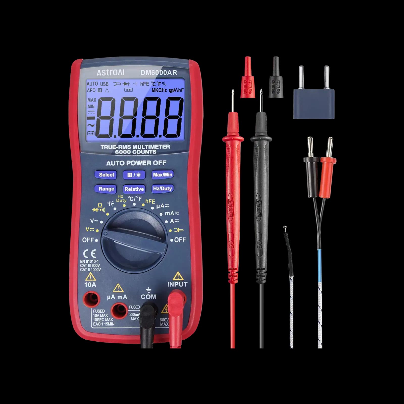
True RMS, 6,000-count, auto-ranging. Our pick for microcontroller and electronics projects.
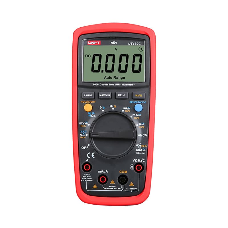
True RMS, 6,000-count, auto-ranging, CAT III 600V. True RMS and auto-ranging at a budget price.

True RMS, auto-ranging, CAT III 600V. The same Fluke reliability as the 117, with capacitance and frequency measurement.
As an Amazon Associate I earn from qualifying purchases. Prices and availability are shown on Amazon.
Frequently asked questions
How accurate should a 5V regulator output be?
It depends on the part. Many 7805-type regulators are specified to stay within a few percent of 5 V over their rated load and input range, which allows readings roughly between 4.8 V and 5.2 V, while precision LDOs can be tighter. The datasheet lists the guaranteed output range under its test conditions.
Can a voltage regulator fail with its output equal to the input?
Yes. If the pass transistor inside a linear regulator fails short, the output follows the input, so a 5 V rail might suddenly read 9 V or 12 V. That can damage everything powered from the rail, so if you see it, disconnect power and check the downstream parts before fitting a new regulator.
Can I test a voltage regulator out of circuit?
Yes, by building a minimal circuit: the input and output capacitors the datasheet recommends, an input voltage comfortably above the output plus dropout, and a load resistor sized for a modest current. Resistance or diode tests on a bare regulator are not meaningful, because it only shows its behavior when powered.
Why does my LM317 output the wrong voltage?
An adjustable regulator sets its output with two resistors, so a wrong or drifted resistor, a broken trimmer or a bad solder joint on the ADJ pin changes the voltage. Check the resistor values against the formula in the datasheet, then confirm the input headroom, as with any linear regulator.
Why does my regulator output read high with no load connected?
Some adjustable regulators, the LM317 among them, need a minimum load current to stay in regulation, and the datasheet gives the figure. With nothing connected and a high-value feedback divider, the output can creep above its setting. Designs usually size the divider so it draws that current on its own. Add a modest load resistor and measure again before blaming the part.


