HOW-TO GUIDE
How to Test a Pressure Switch With a Multimeter
By the OhmSavvy Research Team ·

Safety first: mains voltage and stored pressure
- Well pump and compressor pressure switches often switch mains voltage directly, commonly 120 V or 240 V, on exposed terminals under the cover. The line terminals stay live even when the contacts are open. Switch off and lock the breaker, then prove the terminals dead with a voltage tester.
- Release stored pressure the way the equipment manual describes before removing a switch or its tubing. A compressor tank or a pressure tank can hold a large amount of energy.
- Furnaces have mains-powered parts behind the panel even though the pressure switch circuit is often low voltage. Switch the furnace off at its service switch before disconnecting anything.
- Live voltage tests are for people who are competent to work near exposed live terminals, with a meter and leads rated for the circuit. If that is not you, stop at the dead tests.
How a pressure switch works
Inside the switch, a diaphragm or bellows is connected to the system through a port, a tube or a hose. When pressure (or vacuum) on the diaphragm passes a set point, it pushes against a spring and flips a set of contacts. Many switches have two set points: the cut-in, where the contacts change one way as pressure falls, and the cut-out, where they change back as pressure rises. The multimeter only tests the contacts. A switch with perfect contacts can still fail because its port is blocked or its spring setting has drifted.
01
Isolate
Power off, pressure released
02
Free terminals
Label and lift one wire
03
At rest
Continuity with no pressure
04
Actuated
Continuity with pressure applied
05
Live test
Voltage across the switch
Normally open vs normally closed contacts
"Normally" describes the contacts with no pressure applied, which is how they sit on your bench. The wiring diagram or the switch body usually marks which you have; some switches have both plus a common terminal.
Normally open (NO)
Open with no pressure; closes when pressure or vacuum reaches the set point.
Normally closed (NC)
Closed with no pressure; opens when pressure reaches the set point.
Changeover (SPDT)
A common terminal with one NO and one NC contact; test both pairs.
1Isolate the equipment and release the pressure
Turn the equipment off at its breaker or service switch, lock it off where you can, and verify the switch terminals are dead. Then release pressure as the manufacturer describes. For a typical well system, that means leaving the pump off and opening a tap until the flow stops; for a compressor, it means opening the tank drain or bleed valve. A furnace draft switch holds no stored pressure, but the inducer must be off.
2Identify the terminals and free one wire
Photograph the wiring, label each wire, then disconnect at least one wire from the contact you are testing. Left connected, the switch sits in parallel with the rest of the circuit, so a motor winding or a control board can give a reading even when the contacts are open. Many pump and compressor switches are double-pole, breaking both supply wires through two separate contacts, and each pole needs its own test.
While the wires are off, check insulation as well. Set the meter to its highest resistance range and measure from each terminal to the metal body or the earth terminal. Every reading should be OL. A reading in ohms or kilohms means water or debris has bridged a live part to the body, which is a shock hazard as well as a fault, and the switch should be replaced.
3Check continuity at rest
Set the meter to continuity or the lowest resistance range, short the probes to note the lead reading, then measure across each contact with no pressure on the switch. A normally closed contact should read close to the lead resistance; a normally open contact should read OL.
4Check continuity when actuated
Now make the switch change state and confirm that the readings swap. How you apply pressure depends on the switch. A small vacuum switch, such as a furnace draft switch removed from its hose, can be actuated with a hand vacuum pump on its port. A small air or water switch can sometimes be bench tested with a hand pump and a gauge, staying within the switch's rated pressure. Larger pump and compressor switches are usually easier to test in place with the live method below.
Furnace draft switches are usually marked with the vacuum at which they close, often in inches of water column. Technicians check the other half of the system by connecting a manometer to the switch hose with the inducer running: if the inducer cannot pull at least the marked vacuum, the switch is right to stay open and the cause lies in the inducer, hose or venting. Whichever method you use, watch the meter as the switch changes. The reading should snap cleanly between OL and near zero rather than flickering.
A contact that does not change state at all is faulty, or its port is blocked. A contact that changes but reads several ohms when closed is worn. For a closer look at contact resistance, our guide to measuring resistance across a relay contact explains why a voltage-drop test under load is more telling than an ohms reading.
5Live voltage test across the switch
With the equipment powered and the switch in its normal circuit, set the meter to AC or DC volts to match the circuit. Across a closed contact you should see almost 0 V, because a good contact drops almost nothing. Across an open contact you see close to the full supply voltage, because the load on the other side connects that terminal back to the opposite supply line.
On a double-pole mains switch, it is clearer to measure line to line on the line terminals (the supply should be there) and then on the load terminals (it should match the supply when the contacts close and fall to about zero when they open). The same reasoning is used for limit switches in our limit switch guide.
Well pump, furnace and compressor switches
The behavior below is typical, not universal. The wiring diagram on the equipment, or the switch maker's data, is the authority for your unit. On a boiler, the same continuity method also checks the control stat; see how to test a boiler thermostat with a multimeter.
| Equipment | Contacts with no pressure | When they change | Circuit it switches |
|---|---|---|---|
| Water well pump | Usually closed (pump allowed to run) | Open at cut-out, close again at cut-in | Often mains to the pump, frequently double-pole |
| Air compressor | Usually closed (motor allowed to run) | Open at cut-out, close again at cut-in | Often mains to the motor; may include an unloader valve |
| Furnace draft (vacuum) switch | Usually open | Close when the inducer creates enough vacuum | Often a low-voltage control circuit, commonly 24 VAC |
Many failures on these switches are on the pressure side rather than the electrical side: sediment in a well switch's inlet pipe, a split or water-logged furnace hose, or a leaking compressor check valve. Inspect and clear these before replacing a switch that tests good electrically.
Rapid on-off cycling of a well pump is a common example. The switch is often blamed, but a waterlogged pressure tank or one with the wrong air pre-charge makes pressure rise and fall within seconds, so the switch is simply responding correctly. The tank maker gives the pre-charge setting relative to the switch's cut-in pressure. Contacts that chatter at the moment of switching, on the other hand, are typical of a worn switch, and the arcing soon pits and burns them.
Reading the results
| What you measure | What it means |
|---|---|
| Changes from OL to near 0 Ω (or the reverse) when actuated | Contacts are switching; check the set points and the pressure side |
| Never changes state | Stuck contacts, failed diaphragm or blocked port |
| Closed contact reads several ohms or a changing value | Burnt, pitted or dirty contacts; replace the switch |
| Live: near full supply voltage across a switch that should be closed | Contact open; the switch, its port or its setting is at fault |
| Live: a few volts across a closed switch | Contacts passing current poorly and heating |
| Any resistance from a terminal to the switch body or earth | Insulation fault; replace the switch |
Compare against the set points
Which meter to use
Pump and compressor switches carry mains voltage, so use a meter with a CAT rating suited to the installation and leads in good condition. The meters below are from our best multimeters roundup; furnace work is covered in our best multimeter for HVAC technicians guide.
Meters in our reviews
True RMS, auto-ranging, CAT III 600V. Built for electricians and serious hobbyists.
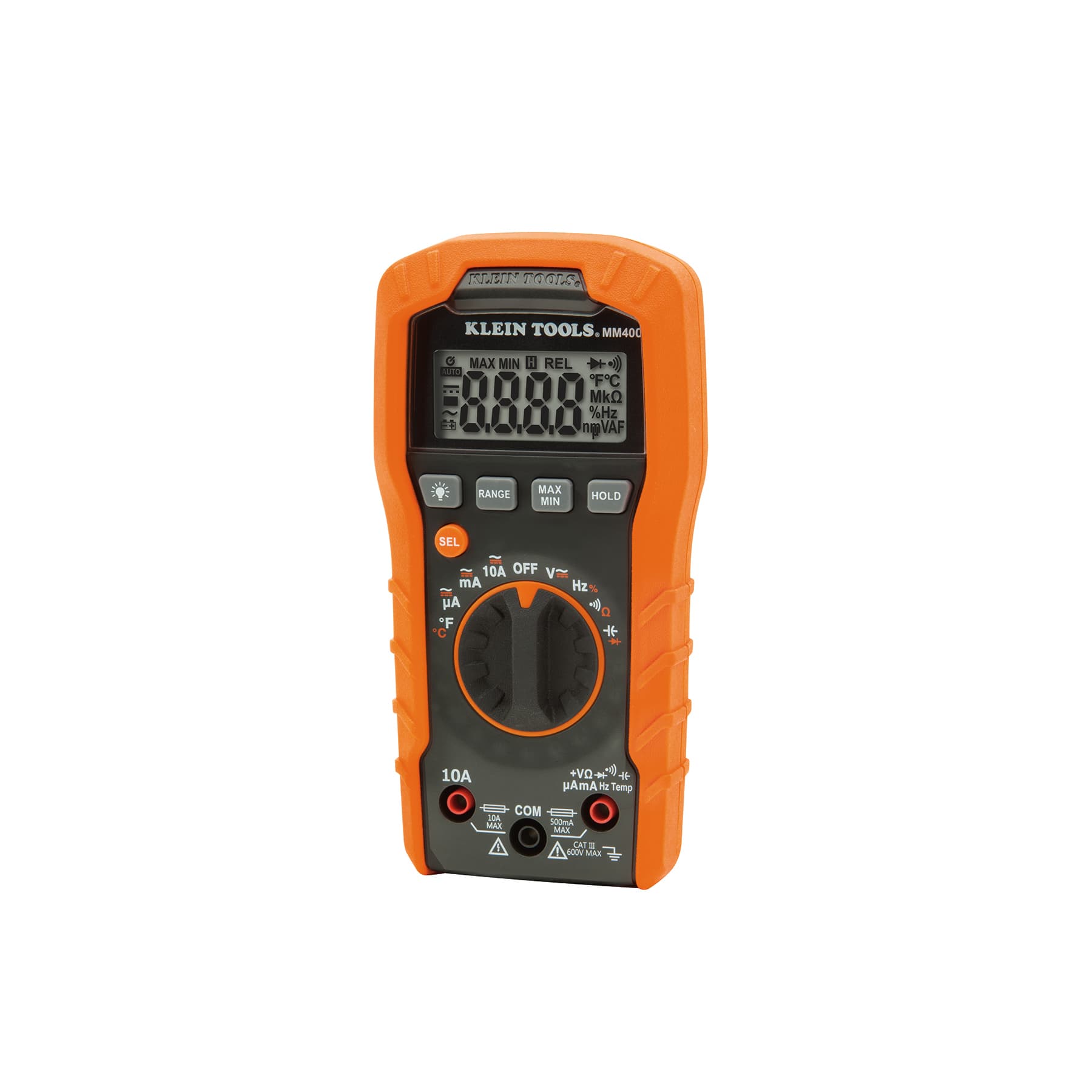
Auto-ranging, CAT III 600V, for tradespeople and home electrical work.

True RMS, CAT III 1000V / CAT IV 600V, with an analog bar graph that shows contacts opening and closing as pressure changes.
As an Amazon Associate I earn from qualifying purchases. Prices and availability are shown on Amazon.
Frequently asked questions
How do I know if my well pump pressure switch is bad?
Typical signs are a pump that will not start when pressure is low, one that will not stop at the cut-out pressure, or chattering contacts. With the power off, look for burnt or pitted contacts and a blocked pressure port. With the power on, a switch that should be closed but has supply voltage on its line side and none on its load side has failed open.
Can I bypass a furnace pressure switch to test the furnace?
Do not run a furnace with its pressure switch bypassed. The switch proves the inducer is moving combustion gases out through the vent, and bypassing it can let flue gases, including carbon monoxide, spill into the home. Test the switch and its hose with the methods on this page, and leave any jumper diagnosis to a qualified technician.
What is the difference between cut-in and cut-out pressure?
Cut-in is the pressure at which the switch turns the pump or compressor on as pressure falls; cut-out is the pressure at which it turns it off as pressure rises. The gap between them is the differential, which stops the equipment from cycling rapidly. The settings are usually printed on the switch or its cover, and some switches can be adjusted.
Why does my furnace pressure switch not close even though it tests good?
If the switch closes when you apply suction on the bench, the problem is usually on the pressure side: a cracked, kinked or water-filled hose, a blocked port on the inducer housing, a weak inducer motor or a blocked vent or condensate drain. These stop the switch from seeing enough vacuum, so it correctly stays open.
How do I adjust a well pump pressure switch?
On the common residential type, switch off and lock out the power first, because the terminals are live. Turning the nut on the large spring clockwise raises cut-in and cut-out together, while the small spring changes only the cut-out, and so the differential. Make small turns, watch a pressure gauge through a full cycle, stay within the switch and tank ratings, and set the tank pre-charge to suit the new cut-in.

