HOW-TO GUIDE
How to Test a Transistor in Circuit With a Multimeter
By the OhmSavvy Research Team ·
Before you start
- Diode and resistance checks are made with the circuit unplugged or the battery removed. A powered circuit can damage the meter on these ranges and gives meaningless readings.
- Power supplies, amplifiers and anything that runs from mains can hold a dangerous charge in large capacitors after unplugging. Discharge them safely, then confirm with the meter on DC volts.
- Only make powered voltage checks on low-voltage circuits you understand. Inside mains equipment, many transistors sit on live circuits; leave those to someone trained to work on them.
A bipolar transistor is two diodes back to back
A bipolar junction transistor (BJT) has three legs: base, collector and emitter. Electrically, the base forms a PN junction with the collector and another with the emitter. In an NPN transistor the base is the P side of both junctions, so both diodes point away from the base. In a PNP transistor the base is the N side, so both diodes point towards it. Between collector and emitter there is no single junction to forward-bias, so a healthy transistor reads open both ways on that pair.
That model is all the meter needs. If you are new to diode mode, our guide to testing a diode with a multimeter explains how the meter pushes a small current through a junction and displays the voltage across it.
1Power off and discharge the circuit
Disconnect the power, remove batteries, and wait for or deliberately discharge any large capacitors. Check across the supply rails on DC volts to confirm they read close to zero before switching to diode mode. Leaving a charged capacitor in place does more than risk the meter: its voltage adds to the meter's test voltage and makes the junction readings drift or jump.
2Identify the pins
Read the part number off the case and look up its datasheet. Pin order is not standard: two transistors in the same TO-92 or SOT-23 package can have base, collector and emitter in different positions, and some board footprints are labeled while others are not. The circuit board's silkscreen or a service schematic often marks them too.
Base (B)
The control pin. Both junctions share it.
Collector (C)
Load current enters (NPN) or leaves (PNP) here.
Emitter (E)
Often tied to ground (NPN) or the supply (PNP).
3Check both junctions in diode mode
Turn the dial to diode test. For an NPN transistor, put the red lead on the base and touch the black lead to the emitter, then to the collector. Both should show a forward voltage, commonly in the region of 0.5 to 0.8 V for a silicon small-signal part. Swap the leads and both should read OL. Finally, check collector to emitter in both directions: it should read OL. For PNP, everything is reversed: the black lead goes on the base for the forward readings.
| Red lead | Black lead | NPN (healthy) | PNP (healthy) |
|---|---|---|---|
| Base | Emitter | ≈ 0.5–0.8 V | OL |
| Base | Collector | ≈ 0.5–0.8 V | OL |
| Emitter | Base | OL | ≈ 0.5–0.8 V |
| Collector | Base | OL | ≈ 0.5–0.8 V |
| Collector | Emitter | OL | OL |
| Emitter | Collector | OL | OL |
A reading near 0 V on any pair, in both directions, means a shorted junction or a short across it. OL in both directions on a base junction means it is open. Power transistors and Darlington transistors read differently: a Darlington has two junctions in series from base to emitter, so it typically reads higher, and many contain internal resistors and a diode across collector and emitter. Check the datasheet's internal diagram before calling one faulty.
Look at the part as well as the numbers. Transistors that have failed from overheating or a surge often show it: a cracked or bulging case, a scorch mark on the board, or discolored solder around the legs. In power stages, a common failure is a collector-emitter short. When you find one, test the parts around it before fitting a replacement. A shorted transistor can take its base resistor, driver stage or emitter resistor with it, and a new transistor dropped into the same fault may fail the moment power returns. Check the load it switches too: a relay coil or motor with shorted windings can be what overloaded the transistor in the first place.
How parallel components distort in-circuit readings
In circuit, the meter's test current does not only flow through the transistor. Every part connected between the same two pins forms another path, and the meter displays the combined result. That is why an in-circuit test can make a good transistor look bad, and occasionally make a bad one look acceptable. The same principle applies to any resistance reading, as our guide to measuring resistance in a parallel circuit explains.
| Part across the pins | What the meter shows | How to read it |
|---|---|---|
| Low-value resistor across B-E | Forward reading lower than normal; reverse may not read OL | Can be normal; compare with the schematic |
| Coil, transformer winding or motor across C-E | Near 0 V both ways, looks shorted | Lift a leg before condemning the part |
| Capacitor across a junction | Reading climbs, then settles or goes OL | Wait for it to settle; discharge first |
| Protection diode across C-E | One forward reading on C-E | Normal in relay and motor drivers |
| Second transistor in parallel | Fault could be either part | Lift one to isolate it |
The best reference in circuit is an identical working circuit. Stereo amplifiers, multi-channel drivers and boards with repeated sections let you test the same transistor position on the good channel and compare. Readings that match closely suggest the parts around both transistors are doing the same thing; a clear difference points to the faulty side.
It also helps to know what diode mode can see. The meter drives a small test current from an open-circuit voltage of a few volts, which varies by model. A parallel resistor of a few hundred ohms takes a large share of that current and drags the reading down, while one of many kilohms usually makes little difference to a forward reading. If the schematic shows a resistor across the junction, a lower reading may be exactly what a good transistor should give in that position.
4Measure Vbe and Vce with the circuit powered
When the power-off checks are clouded by parallel parts, voltage measurements on a running low-voltage circuit can settle the question, because they show what the transistor is actually doing. Switch to DC volts, put the black lead on the emitter and the red lead on the base for Vbe, then on the collector for Vce. Clip the black lead on so a slipping probe cannot short adjacent pins. The table assumes a silicon NPN transistor used as a switch with its emitter at ground; the figures are typical, so compare with the datasheet and the circuit's design.
| Vbe | Vce | Likely meaning |
|---|---|---|
| ≈ 0.6–0.75 V | Low, often ≈ 0.1–0.3 V | Switched fully on (saturated): working |
| ≈ 0 V | ≈ supply voltage | Off, no base drive: working if it should be off |
| ≈ 0.6–0.75 V | ≈ supply voltage | Driven but not conducting: suspect an open C-E path |
| ≈ 0 V | ≈ 0 V | On with no drive: suspect a C-E short, or check the load |
| Well above 1 V (not a Darlington) | Any | Junction not clamping: suspect an open B-E junction |
In amplifier stages the transistor is biased partly on, so Vce sits somewhere between the rails rather than at either end. There the useful comparison is with the voltages printed on a service schematic, or measured on a working channel.
When to lift a leg or remove the transistor
Lift a leg when a junction reads shorted or abnormally low and the circuit has parts that could explain it, when the powered checks disagree with the diode checks, or when you are about to replace the part anyway. Desolder one leg, usually the base, and bend it clear of its pad; that isolates both junctions from the drive circuit. If you remove the part completely, our guides to removing solder from a circuit board and clearing a plated through-hole help you do it without lifting pads.
01
Power off
Discharge, confirm 0 V
02
Diode checks
B-E, B-C, C-E both ways
03
Powered checks
Vbe and Vce, low voltage only
04
Lift a leg
Usually the base
05
Retest alone
Diode mode out of circuit
Replace like for like
MOSFETs are a different test
Everything above applies to bipolar transistors. A MOSFET has a gate, drain and source; its gate is insulated, so there is no base junction to measure, and most power MOSFETs have a body diode between source and drain. Testing one means checking that body diode and using the meter's test voltage to charge the gate and switch it on. Our step-by-step guide covers it: how to test a MOSFET with a digital multimeter. If you are unsure which type you have, the datasheet for the part number settles it.
Which meter to use for transistor testing
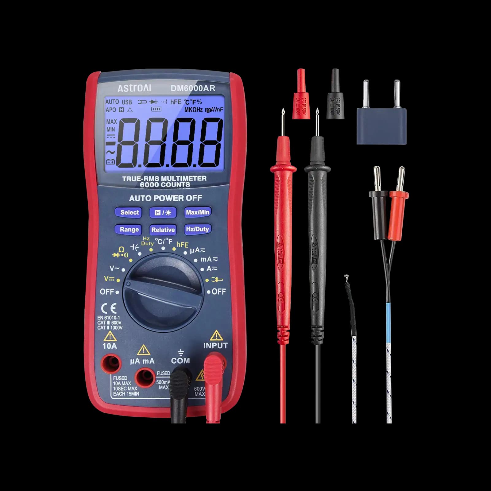
A diode-test position and a reasonably fast, readable display are what matter here; most digital meters have both. A higher count helps you see small differences between a good and a suspect junction. The meters below are from our best multimeters roundup, and how to use a multimeter covers the dial and jacks if you are starting out.
Meters in our reviews
True RMS, 6,000-count, auto-ranging. Our pick for microcontroller and electronics projects.
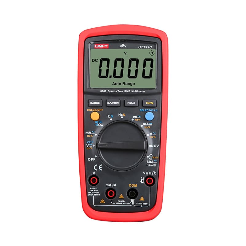
True RMS and auto-ranging with a 6,000-count display and a CAT III 600V rating, at a budget price.

True RMS, auto-ranging, CAT III 600V. Fluke reliability, with capacitance and frequency measurement.
As an Amazon Associate I earn from qualifying purchases. Prices and availability are shown on Amazon.
Frequently asked questions
Can a transistor test good with a multimeter and still be faulty?
Yes. Diode mode only checks the junctions at the meter's small test current. A transistor can pass that test and still have low gain, leak at operating voltage, or fail only when it heats up. If the junctions look fine but the circuit still misbehaves, compare its powered voltages with a working circuit or substitute a known-good part.
Can I use the hFE socket on my meter to test a transistor?
Only out of circuit, and only on meters that have one. The socket measures current gain at a single low test current, so it confirms the part works and is the right type, but the figure can differ from the gain in your circuit. Gain also varies widely between transistors of the same part number, so treat it as a rough check.
Which leg of a transistor should I lift to test it in circuit?
Lifting the base is usually enough, because it disconnects both junctions from the parts that drive the base. If the collector-emitter path still reads low with the base lifted, something else is connected across collector and emitter, and you need to lift a second leg or remove the transistor completely to be sure.
How do I tell if a transistor is NPN or PNP with a multimeter?
Find the pin that conducts to both other pins in diode mode; that is the base. If the readings appear with the red lead on the base, it is NPN. If they appear with the black lead on the base, it is PNP. Confirm the result against the datasheet, because the pin order varies between packages and manufacturers.
Can I test a transistor with a meter that has no diode mode?
Usually, with care. Use a resistance range and look for the same pattern as the diode test: low in one direction across each junction, high in the other, and high both ways from collector to emitter. Some digital meters apply too little voltage on their low ohms ranges to forward-bias a silicon junction, so try a higher range and compare against a known-good part rather than trusting absolute numbers.


