HOW-TO GUIDE
How to Test a Thermistor With a Multimeter
By the OhmSavvy Research Team ·
Power off and discharge before you probe
- Resistance mode only works on an unpowered circuit. Unplug the device or remove the battery before measuring, or the reading is meaningless and the meter can be damaged.
- Inrush-limiting NTC thermistors sit at the mains input of many power supplies, right next to large capacitors that can hold a dangerous charge after unplugging. Discharge them safely before touching anything, and let the thermistor cool: inrush limiters run hot in normal use.
- Warm parts with your fingers or a hair dryer on a low setting, not a flame or soldering iron.
NTC vs PTC thermistors
A thermistor is a resistor whose value changes strongly with temperature. Which way it changes decides how you interpret the test:
Washing machines often mount an NTC sensor directly on the heating element; testing a washing machine heating element covers checking both.
| Type | As it warms | Common uses | Warming test should show |
|---|---|---|---|
| NTC (negative temperature coefficient) | Resistance falls | Temperature sensing, inrush current limiting | Reading drops |
| PTC (positive temperature coefficient) | Resistance rises, often sharply above a switching temperature | Resettable fuses, heaters, motor and degauss circuits | Reading rises |
Sensing NTCs are the most common type in repair work: battery packs, 3D printer hotends and beds, appliance and HVAC sensors, and chargers all use them. The steps below focus on NTCs, with notes on PTCs where the test differs.
1Find the rated value
A thermistor's rating is its resistance at a reference temperature. For common NTCs that reference is 25 °C, so a "10k" NTC is 10 kΩ at 25 °C. You may also see it written as R25, or marked with a code such as 103. Other common values include 2.2k, 47k and 100k.
R25
Resistance at 25 °C, the number you compare against. 10k means 10 kΩ at 25 °C.
B value
How steeply resistance changes with temperature. 3950 is a common figure for 10k NTCs.
Tolerance
How far R25 may be from nominal. 1%, 3% and 5% parts are all common: check the datasheet.
If the part is unmarked, the service manual, the device's firmware settings (common for 3D printers) or the replacement part listing usually names it.
2Measure resistance at room temperature
Set the meter to Ω. On an auto-ranging meter it will choose the range; on a manual meter pick the lowest range above the rated value, for example 20 kΩ for a 10k part. Let the thermistor sit untouched for a minute so it settles at room temperature, then touch one probe to each lead. Hold the probes by their insulated handles: your fingers on the tips warm the part and add your own body resistance in parallel.
Remember that room temperature is rarely exactly 25 °C. A 10k NTC in a 22 °C room will read higher than 10 kΩ, about 11.4 kΩ for a typical B3950 part. That is correct behavior, not a fault.
Also allow for tolerance. A 5% 10k part may read anywhere from 9.5 kΩ to 10.5 kΩ at exactly 25 °C, before your meter's own accuracy is added. In practice, a room-temperature reading within about 10% to 20% of the expected value for that temperature is a reasonable pass for a quick check; a reading several times too high or too low is not. The small test current a multimeter uses on resistance ranges normally causes negligible self-heating in a sensing thermistor, so the reading should settle and stay put.
3Do the warming test
With the probes still connected, warm the thermistor body by pinching it between your fingers or aiming a hair dryer at it from a safe distance. Watch the display. An NTC's resistance should fall smoothly and steadily; a PTC's should rise. Remove the heat and the reading should drift back toward the room-temperature value.
01
Power off
Unplug, discharge, let it cool
02
Find rating
e.g. 10 kΩ at 25 °C
03
Room reading
Close to rating for the temperature
04
Warm it
NTC falls, PTC rises
05
Cool it
Reading returns
Want a precise check?
Typical readings for a 10 kΩ NTC thermistor
The values below are calculated for a typical 10 kΩ, B3950 NTC using the standard B-value equation. Real parts follow their own datasheet curve, which can differ by a few percent, especially far from 25 °C, and part tolerance adds more. Treat them as a guide to the shape of the curve, not limits.
| Temperature | Typical resistance (10k, B3950) | Compared with R25 |
|---|---|---|
| 0 °C | ≈ 33.6 kΩ | About 3.4× higher |
| 10 °C | ≈ 20.2 kΩ | About 2× higher |
| 20 °C | ≈ 12.5 kΩ | Higher |
| 25 °C | 10.0 kΩ | Rated value |
| 30 °C | ≈ 8.04 kΩ | Lower |
| 37 °C | ≈ 5.99 kΩ | About 0.6× |
| 50 °C | ≈ 3.59 kΩ | About 0.36× |
| 100 °C | ≈ 0.70 kΩ (698 Ω) | About 0.07× |
Good, open, shorted or drifted: reading the result
| What the meter shows | What it usually means |
|---|---|
| Close to the expected value, changes smoothly with heat | Good part |
| OL or 1 (over range) on every range | Open circuit: cracked body, broken lead or failed joint |
| Near 0 Ω | Shorted part, or a short elsewhere if measured in circuit |
| Plausible value that does not change with heat | Dead or drifted part; also check you are on Ω mode |
| Far from the expected value at a known temperature | Drifted out of tolerance, or the wrong part was fitted |
| Jumps erratically when the part is still | Intermittent crack or poor contact; flex the leads gently and watch |
An open circuit is a frequent failure in sensing NTCs, particularly where leads flex, as on 3D printer hotends. Inrush limiters in power supplies can also crack and go open after a surge. If you suspect the wiring rather than the part, the continuity checks in how to test electrical wires will separate the two.
Testing a PTC thermistor
PTC parts are tested the same way, but the numbers look different. Polymer resettable fuses (often called polyfuses) typically read a very low resistance when cold, often well under an ohm to a few ohms depending on the rating, so zero the meter leads first by shorting them and noting the lead resistance. Ceramic PTCs used in heaters, motor start and degauss circuits usually read higher cold values; the datasheet or service manual gives the expected figure.
The warming test is less dramatic below the switching temperature: many PTCs change only slightly until they reach it, then rise steeply. A gentle warming that barely moves the reading is not necessarily a fault. The clearer failure signs are the same as for an NTC: OL when cold means open, and a resettable fuse that stays at a high resistance long after it has cooled has not reset and should be replaced.
Common thermistor testing mistakes
- Expecting exactly the rated value at room temperature. The rating applies at 25 °C only.
- Holding the probe tips or the part, which warms it and adds body resistance in parallel.
- Measuring with the device powered, which gives a false reading and can damage the meter.
- Condemning a part on a low in-circuit reading without lifting a leg or unplugging it.
- Replacing a thermistor with one that matches the resistance but not the B value or type.
- Reading the wrong range on a manual meter, so a cold NTC above 20 kΩ shows as over range.
In-circuit vs out-of-circuit testing
Measured on the board, the meter sees the thermistor in parallel with everything else connected between those two points, such as bias resistors or an input pin. That usually makes the reading lower than the part alone. A low in-circuit reading is therefore not proof of a fault.
- Plug-in sensors (common in printers, appliances and battery packs): unplug the connector and measure across the sensor's pins. This is effectively out of circuit.
- Soldered parts: lift one leg with a soldering iron and measure the part on its own. A good reading out of circuit points the fault elsewhere.
- Quick in-circuit check: an in-circuit OL usually does mean the thermistor is open, since parallel paths can only lower the reading. An in-circuit reading that still falls with warming is a good sign.
The same rules apply to any component check; our guide to testing a capacitor with a multimeter uses the same in-circuit caution.
Which multimeter you need to test a thermistor
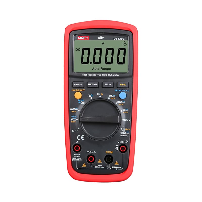
Any working digital meter with a resistance range will do the basic test. A display with more counts shows small changes more finely, which helps when you are watching a reading move during the warming test, and auto-ranging saves stepping through ranges as a cold NTC climbs past 20 kΩ. If your meter has a temperature function with its own probe, it can stand in for the reference thermometer. For what accuracy you really need, see multimeter accuracy for electronics repair, or compare meters in our best multimeters roundup.
Budget meters in our reviews
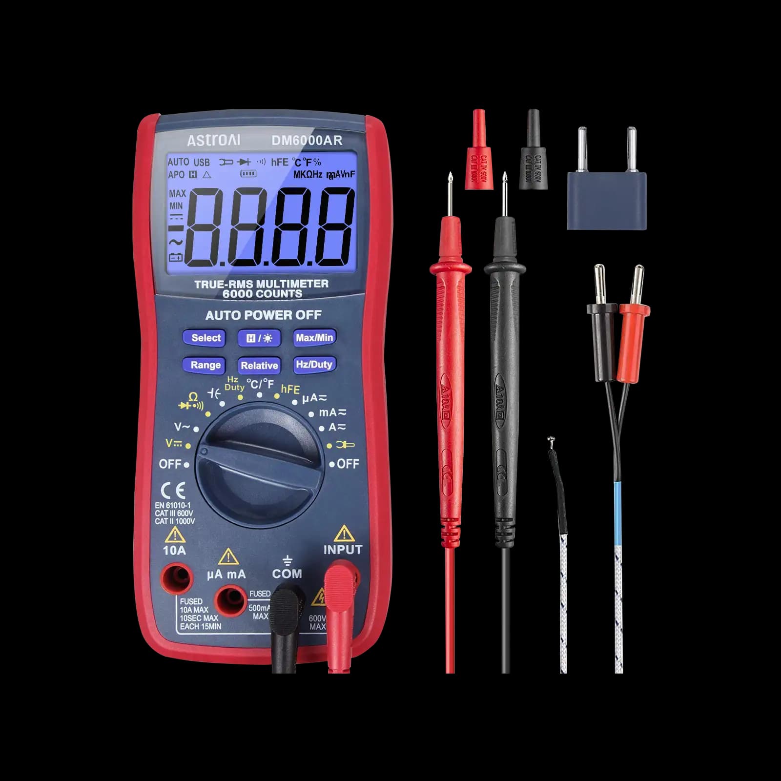
True RMS, 6,000-count, auto-ranging. Aimed at low-voltage microcontroller and electronics projects.
True RMS, 6,000-count, CAT III 600V and auto-ranging, for budget-conscious buyers who still want True RMS.

True RMS, CAT II 600V, auto-ranging. Our budget pick for home use and beginners.
As an Amazon Associate I earn from qualifying purchases. Prices and availability are shown on Amazon.
Frequently asked questions
What does 103 mean on a thermistor?
It is usually the standard three-digit resistance code: the first two digits are the value and the third is the number of zeros. So 103 means 10 followed by three zeros, or 10,000 Ω, which is 10 kΩ at the reference temperature, normally 25 °C. Confirm against the datasheet or the device service manual where you can.
What is the B value of a thermistor?
The B value (or beta) describes how steeply an NTC thermistor's resistance changes with temperature. Two parts can both be 10 kΩ at 25 °C but read differently at 0 °C or 50 °C if their B values differ. When replacing a thermistor, match both the resistance rating and the B value given in the datasheet.
Why does my thermistor reading keep changing?
Usually because the part is changing temperature. Holding the body or the probe tips with your fingers warms it, and air drafts cool it. Let the part sit untouched for a minute, hold the probes by their insulated handles, and read once the display settles. A reading that jumps erratically even when stable can point to a cracked part or poor contact.
Can a bad thermistor stop a battery pack from charging?
It can. Many battery packs and chargers use a thermistor to monitor cell temperature. If it fails open, the charger may read it as extremely cold; if shorted, as extremely hot. Either way, the protection circuit may refuse to charge. Check the thermistor between its pack terminals against the value the pack or charger documentation specifies.
How much do I need to warm a thermistor to test it?
Only a few degrees. Holding a small NTC between your fingers usually shifts its resistance by several percent within seconds, which is enough to show it responds. A hair dryer on a low setting gives a larger change. Avoid flames and direct contact with a soldering iron, which can exceed the part's temperature rating or crack it.



