HOW-TO GUIDE
How to Test a MOSFET With a Digital Multimeter
By the OhmSavvy Research Team ·
Before you start: power off, discharge, and mind static
- MOSFETs are often found in power supplies, motor drivers and inverters. Unplug the equipment and make sure large capacitors on the board are discharged before you touch anything. Our capacitor testing guide explains how to discharge one safely and confirm 0 V.
- Never take diode or resistance readings on a powered circuit. The meter supplies its own small test voltage; an external voltage gives false readings and can damage the meter.
- The gate is sensitive to static. Touch a grounded metal object before handling a loose MOSFET and keep spares in their antistatic packaging.
N-channel vs P-channel, and which pin is which
This guide covers ordinary enhancement-mode power MOSFETs, the kind used as switches in most hobby and repair work. They come in two polarities. An N-channel MOSFET turns on when the gate is driven positive relative to the source; a P-channel turns on when the gate is driven negative relative to the source. Both have three terminals:
Gate (G)
The control terminal. Insulated from the other two, so it behaves like a tiny capacitor rather than a conductor.
Drain (D)
One end of the switched channel. On many TO-220 and similar packages the metal tab is also the drain.
Source (S)
The other end of the channel, and the reference the gate voltage is measured against.
Pin order is not standardized. Many TO-220 power MOSFETs are gate, drain, source from left to right when viewed from the printed side, but plenty are not, so look up the part number on the body and check the datasheet before you test. Every power MOSFET also contains a body diode between source and drain, a by-product of how it is built. Its direction depends on the polarity, and it is the basis of the first test.
| N-channel | P-channel | |
|---|---|---|
| Turns on when the gate is | Positive relative to source | Negative relative to source |
| Body diode points | From source (anode) to drain (cathode) | From drain (anode) to source (cathode) |
| Body diode reads forward with | Red on S, black on D | Red on D, black on S |
| To charge the gate on | Black on S, touch red to G | Red on S, touch black to G |
| To check it switched on | Red on D, black on S | Red on S, black on D |
1Handle it safely and discharge the gate
The gate is separated from the channel by an extremely thin layer of oxide. That insulation is what lets a MOSFET switch with almost no gate current, and it is also why a static spark can ruin one. Ground yourself, pick the part up by its body, and avoid touching the gate pin with a dry fingertip.
Because the gate is insulated, it can hold a charge, and a charged gate may leave the channel partly or fully on. That makes a good part look shorted. Before any measurement, briefly connect the gate to the source with a probe tip, a pair of metal tweezers or a short wire. Do the same between every test step below; it takes a second and removes the most common source of confusing readings.
2Check the body diode in diode mode
Set the dial to diode test, the position marked with the diode symbol, usually shared with continuity. If diode mode itself is new to you, our guide to testing a diode with a multimeter explains what the number means. For an N-channel part, put the red probe on the source and the black probe on the drain. The body diode is now forward biased and the meter shows its forward voltage, typically a few tenths of a volt, often around 0.4 to 0.8 V depending on the part and the meter's test current. Swap the probes and a healthy, discharged MOSFET reads OL. For a P-channel part, reverse both probe positions.
Then check the gate. Gate to source and gate to drain should both read OL in both directions, because the gate is insulated from everything else. Any voltage reading or beep involving the gate means the oxide has broken down. Some MOSFETs have protection diodes built in between gate and source, which do give a diode reading; the datasheet's internal diagram shows whether yours does.
3Switch it on with gate charge
The body-diode check proves the junction is intact, but not that the transistor switches. For that, use the meter's diode-mode voltage to charge the gate. For an N-channel MOSFET, put the black probe on the source and touch the red probe to the gate for a moment. The gate now holds a positive charge relative to the source. Without touching the gate, move the red probe to the drain: a working MOSFET now reads close to zero, or beeps, in the direction that read OL a minute ago. Short gate to source and it should return to OL.
01
Short G to S
Remove any stored gate charge
02
Red D, black S
Channel off: reads OL
03
Black S, red to G
Charges the gate positive
04
Red D, black S
Channel on: near zero or beep
05
Short G to S
Channel off: OL again
For a P-channel MOSFET, reverse the polarities: red probe on the source, touch the black probe to the gate to charge it negative, then measure with red on the source and black on the drain.
This test depends on your meter
Reading the results: shorted, open or healthy
Power MOSFETs most often fail short, usually between drain and source, after overheating or a voltage spike. Gate damage comes next, frequently from static or from a gate driven past its rated voltage. The table assumes an N-channel part with the gate discharged before each check; swap the probe colors for P-channel.
| What you see | Likely condition | Next step |
|---|---|---|
| Body diode forward reading, OL reversed, gate OL to D and S, switches on and off | Healthy | Look elsewhere for the fault |
| Near zero or beep D to S in both directions, even after shorting G to S | Shorted drain-source | Replace; also check what drove it |
| Any reading between gate and drain or gate and source (no built-in gate diode) | Gate oxide damaged | Replace |
| OL D to S in both directions and it never switches on | Open | Replace; inspect leads and joints first |
| Body diode fine but it will not switch on | Inconclusive: threshold may be above the meter's voltage | Retest with a known gate voltage |
| Switches on but stays on after G is shorted to S | Leaky or damaged channel | Replace |
A shorted MOSFET is rarely the whole story. Gate driver chips, gate resistors and the load itself often fail with it, so check those before fitting a new part and switching on.
Know the limits of a pass, too. The meter's test current is typically around a milliamp, so it says nothing about how the part behaves at the amps it carries in service. It cannot measure the on-resistance (RDS(on)) at full gate drive, the voltage rating, or how the MOSFET switches at speed. A part that passes every check here is very probably sound, but a weakened MOSFET that only misbehaves when hot or under full load needs testing in its circuit, or simply replacing with the same part number.
Testing a MOSFET while it is still in circuit
A quick in-circuit check can find a dead short, but it cannot pass a part. Three things get in the way:
- Parallel paths. Other MOSFETs, diodes, windings and resistors connected across drain and source change the readings, the same problem covered in measuring resistance in a parallel circuit. A near-zero reading on one MOSFET in a bridge may be its neighbor.
- Gate pull-down resistors. Most circuits fit a resistor from gate to source so the MOSFET stays off when undriven. It drains the charge from the meter almost immediately, so the gate-charge test fails on good parts.
- Gate drivers and capacitance. A driver chip or capacitors on the gate line make the gate readings meaningless.
If an in-circuit drain-source reading is suspiciously low, desolder the MOSFET, or at least lift its drain or source, and repeat the full test on the bench. A short that remains with the part out of circuit is conclusive. If you see OL where you expected a reading, our page on what OL means on a multimeter covers the other causes.
Which meter to use for MOSFET testing
Any digital multimeter with a diode-test mode can run both checks; the main difference between models for this job is the diode-mode test voltage, which decides whether the gate-charge test can switch a standard power MOSFET on. Check the manual for that figure. The meters below are from our best multimeters roundup, and the multimeter buying guide explains display counts, True RMS and CAT ratings.
Meters in our reviews
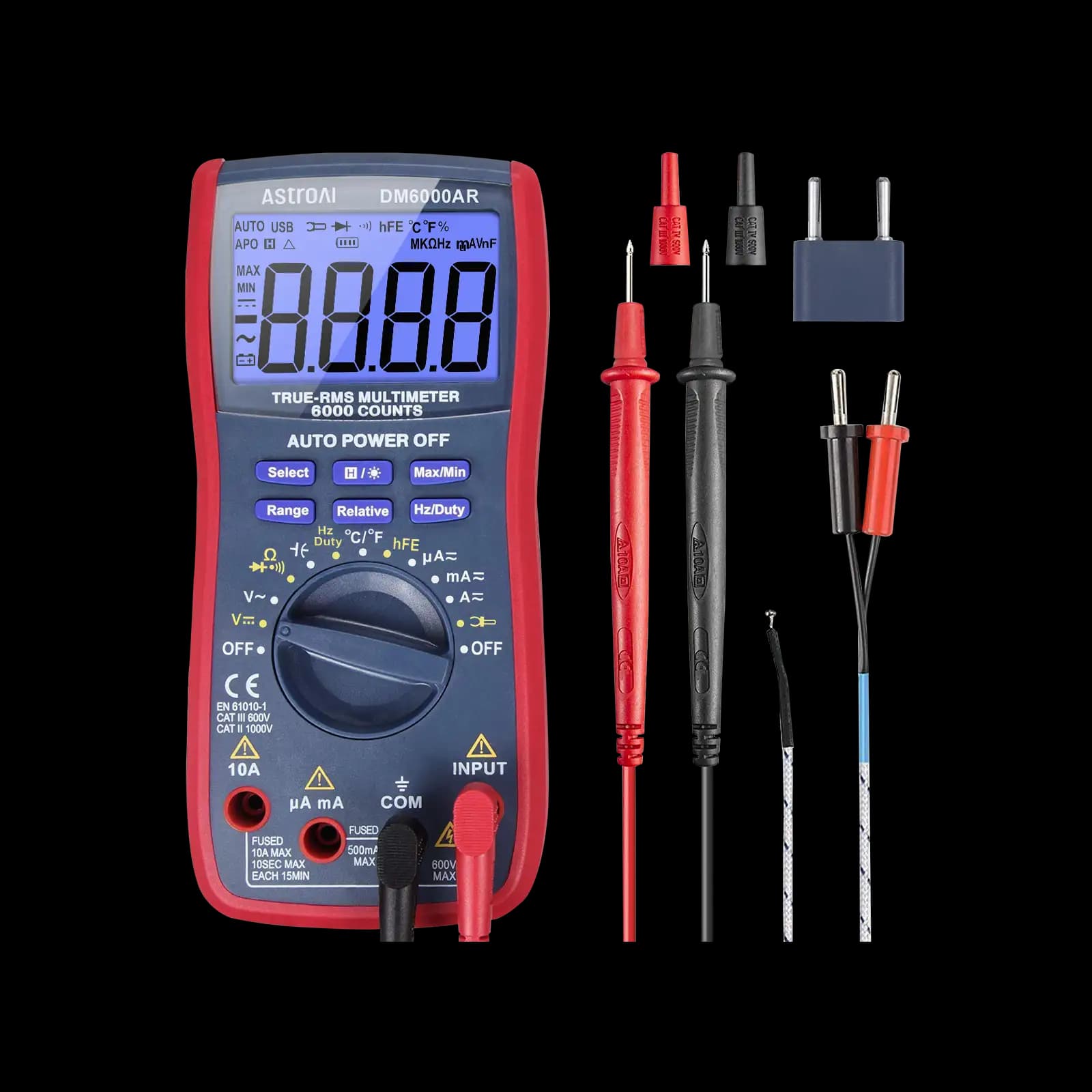
True RMS, 6,000-count, auto-ranging. Our pick for low-voltage microcontroller and electronics projects.
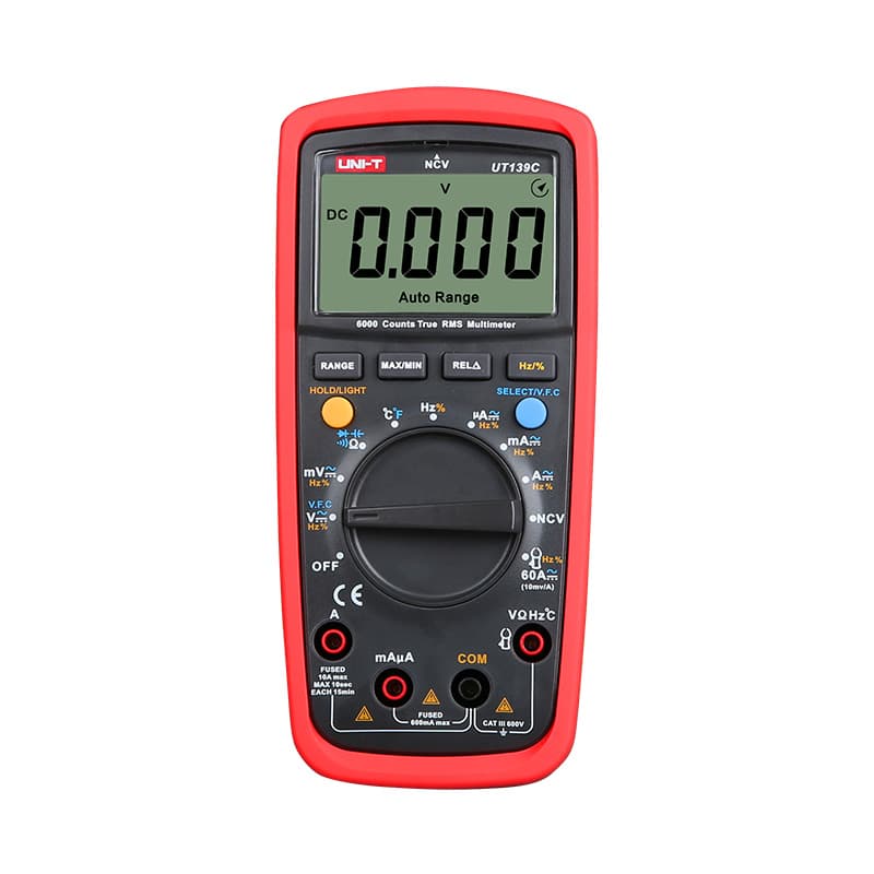
True RMS and auto-ranging with a 6,000-count display and a CAT III 600V rating, at a budget price.

True RMS, auto-ranging, CAT III 600V. The 117's reliability without NCV or LoZ, for field and electronics work.
As an Amazon Associate I earn from qualifying purchases. Prices and availability are shown on Amazon.
Frequently asked questions
What reading should a good MOSFET show in diode mode?
With the probes across the body diode in its forward direction, a healthy power MOSFET usually shows a few tenths of a volt, often somewhere around 0.4 to 0.8 V. In the reverse direction, with the gate discharged, it should read OL. The gate should read OL to both the drain and the source in both directions.
Why does my MOSFET read shorted between drain and source?
First short the gate to the source and test again, because a charged gate can leave the channel switched on. If the low reading persists out of circuit, the device is shorted, which is the most common way power MOSFETs fail. In circuit, a parallel part such as another MOSFET, a diode or a winding may be the real cause.
Can static electricity damage a MOSFET?
Yes. The gate is insulated from the channel by a very thin oxide layer, and a static discharge you cannot even feel can puncture it. Damage is not always total; it can leave a gate that leaks or a threshold that has shifted. Touch a grounded metal object first, hold the part by its body and store it in antistatic packaging.
Why won't my MOSFET turn on during the multimeter test?
The most likely reason is that your meter's diode-mode voltage is lower than the MOSFET's gate threshold, which is common with standard-threshold power parts. Logic-level MOSFETs switch on more easily. It can also mean the gate charge leaked away, you charged the gate with the wrong polarity, or the gate is damaged. Treat a no-turn-on result as inconclusive, not a failure.
Can a MOSFET fail open?
It can, though shorts are more common. An open MOSFET reads OL across the body diode in both directions and never switches on, often because a bond wire inside the package has burned through after an overload. Physical damage such as a cracked package or a lifted lead gives the same reading, so check the leads and solder joints too.


