HOW-TO GUIDE
How to Check a Motor Winding for a Short With a Multimeter
By the OhmSavvy Research Team ·

Safety first: motors, drives and capacitors
- Lock out and tag out the supply at the isolator, then prove it dead with a voltage tester at the motor terminals before you touch anything. Resistance tests are only ever made on a dead circuit.
- A variable frequency drive (VFD) keeps its DC bus capacitors charged after the supply is switched off. Wait the discharge time given in the drive manual and measure zero volts before disconnecting the motor leads.
- Single-phase motors with start or run capacitors can hold a charge too. Discharge the capacitor safely, following the equipment manual, before testing.
- A permanent-magnet or DC motor generates voltage when its shaft turns. Keep the shaft still while measuring, or the reading is meaningless and the meter can be stressed.
The whole procedure follows the same order every time: isolate, measure the windings against each other, measure them against the frame, and escalate to better test equipment when the meter passes a motor that is still misbehaving.
01
Lock out
Isolate, prove dead, discharge
02
Disconnect
Lift leads from drive or starter
03
Winding vs winding
Readings should match closely
04
Winding vs frame
Should read OL
05
Escalate
Insulation or surge test if needed
1Lock out and disconnect the motor
Once the supply is locked off and proven dead, open the motor terminal box and disconnect the supply cable or lift the motor leads at the starter or drive. Measuring with the cable still connected puts the contactor, overload, drive output or other loads in parallel with the windings, and those paths change the reading. Photograph the connections first so they go back the same way, including any links between terminals.
2Identify the winding leads
The nameplate or the diagram inside the terminal box cover shows how the windings are brought out. A simple three-phase motor has three leads, usually marked T1, T2, T3 or U, V, W. Six- and nine-lead motors bring out both ends of each winding, joined by links for star (wye) or delta. If you can remove the links, you can measure each winding on its own, which gives clearer readings. A single-phase motor has run and start windings, usually with a common lead, covered further down.
3Compare winding-to-winding resistance
Set the meter to its lowest resistance range, short the probe tips together and press REL (or note the lead reading) so lead resistance is subtracted; the method is in our guide to measuring resistance in ohms. Then measure T1 to T2, T2 to T3 and T1 to T3, pressing the probes firmly onto clean metal.
On a star-connected motor each reading is two windings in series; on a delta motor it is one winding in parallel with the other two. Either way, the three readings should be close to equal. Guidance commonly treats a spread of more than a few percent as worth investigating, but the motor manufacturer or rewind shop sets the actual limit. Take all readings at the same time, because copper resistance rises with temperature, and a motor that has just been running reads higher than one that has cooled.
A reading of OL on any pair means an open circuit: a broken winding, a burnt connection or a loose lead. Our page on what OL means on a multimeter covers the display itself. A single coil, such as a valve solenoid, has nothing to compare against, so it is judged against its rated value instead; see how to test a solenoid valve coil resistance.
Worked comparison: reading the imbalance
A simple way to express the spread is the largest difference from the average, divided by the average. These are illustrative readings from star-connected motors, not values for any particular model.
| Motor | T1–T2 | T2–T3 | T1–T3 | Imbalance | What it suggests |
|---|---|---|---|---|---|
| A | 4.20 Ω | 4.22 Ω | 4.18 Ω | ≈ 0.5% | Balanced; move on to the frame test |
| B | 4.20 Ω | 3.70 Ω | 3.70 Ω | ≈ 8.6% | Both readings involving T3 are low: suspect the T3 winding |
| C | 4.20 Ω | OL | OL | n/a | Open in the T3 winding or its connection |
| D | 0.62 Ω | 0.63 Ω | 0.62 Ω | ≈ 1.1% | One count apart: below what the meter can resolve |
For motor B the average is (4.20 + 3.70 + 3.70) ÷ 3 ≈ 3.87 Ω, the largest difference is 4.20 − 3.87 = 0.33 Ω, and 0.33 ÷ 3.87 ≈ 8.6%. The pattern matters more than the percentage: in a star motor, the winding common to both low readings is the suspect, here T3.
Motor D shows the limit of the method. On larger motors the windings read below an ohm, and a meter with 0.01 Ω or 0.1 Ω resolution, plus some variation in probe contact, cannot separate a healthy winding from a slightly shorted one. Low-resistance ohmmeters that use a four-wire connection are made for exactly this.
4Test each winding to the frame
Switch to the highest resistance range. Put one probe on bare metal of the motor frame, such as the earth terminal or a scraped spot free of paint, and touch the other probe to each motor lead in turn. Keep your fingers off both probe tips, or the meter reads your body resistance. A healthy winding reads OL, meaning the resistance to the frame is above the meter's highest range.
A winding that reads a definite resistance to the frame has a ground fault and should not be re-energised. Damp windings can read low as well, and a motor that has stood in a wet location may recover after drying, but that is a decision for an insulation test, not the multimeter. The same frame test is used on appliances; see measuring the resistance of a heating element.
What a multimeter cannot see
A winding contains many turns of wire. If two adjacent turns short together, the resistance drops by only the share of wire they bypass, which can be a fraction of a percent: less than the normal spread between readings. Yet that shorted loop behaves like a shorted transformer secondary when the motor runs, carrying high current and overheating until the insulation around it fails.
Insulation is the other blind spot. A multimeter measures resistance with a few volts at most. Insulation that is cracked, contaminated or damp can read OL at that voltage and still break down at the motor's operating voltage and its switching spikes. An insulation resistance tester, often called a megger, applies a DC test voltage chosen for the motor's voltage rating and reads the leakage in megohms; the test voltage and pass limit come from the motor manufacturer or the applicable standard.
| Fault | Multimeter catches it? | Better tool |
|---|---|---|
| Open winding or broken lead | Yes, OL between leads | Multimeter is enough |
| Hard short from winding to frame | Yes, a reading instead of OL | Insulation tester to confirm |
| Many shorted turns in a small winding | Sometimes, as one low reading | Low-resistance ohmmeter, inductance comparison |
| A few shorted turns in a large winding | Rarely | Surge tester, running current per phase |
| Weak or damp insulation | Usually not, still reads OL | Insulation resistance tester |
Use the running current as a cross-check
Single-phase motors: start and run windings
Single-phase induction motors have a run winding and a start (auxiliary) winding, often with a common lead, and their resistances are not supposed to match. The start winding usually uses finer wire and reads higher than the run winding, though the actual values come from the manufacturer. The useful check is internal consistency: with leads common (C), start (S) and run (R), C–S plus C–R should equal S–R, because S–R measures both windings in series.
A start winding that reads OL, or a sum that does not add up, points to a fault. Failed start or run capacitors and stuck centrifugal switches cause many of the same symptoms as a bad winding, so check them too; see how to test a capacitor with a multimeter and, for HVAC and appliance fans, how to test a fan motor capacitor. Fan motors on electronics are a different case, covered in how to test a 4 wire fan motor.
DC motors: field, armature and brushes
On a wound-field DC motor, measure the field winding on its own terminals and compare it with the manufacturer's figure or an identical motor. The armature is tested at the commutator: with the brushes lifted or removed, measure between adjacent commutator bars all the way round. The readings should be very similar; a markedly low pair suggests a shorted coil, and a high or OL pair suggests an open coil or a broken connection to that bar. These are small resistances, so null the leads first.
For small brushed permanent-magnet motors, measure across the two terminals and turn the shaft slowly by hand between readings. A reading that jumps to OL at certain positions points to worn brushes, a dirty commutator or an open armature coil. Finally, test the terminals and the armature to the frame, exactly as for an AC motor.
Which meter to use
Motor work happens on industrial and building supplies, so choose a meter whose CAT rating suits the installation, with a clear low-resistance range and a REL function for nulling the leads. The meters below are from our best multimeters roundup, and our best multimeter for electricians guide compares them for trade use.
Meters in our reviews
True RMS, CAT III 1000V / CAT IV 600V. The step-up pick for daily professional and industrial use.

True RMS, auto-ranging, CAT III 600V. The meter working electricians buy with their own money.
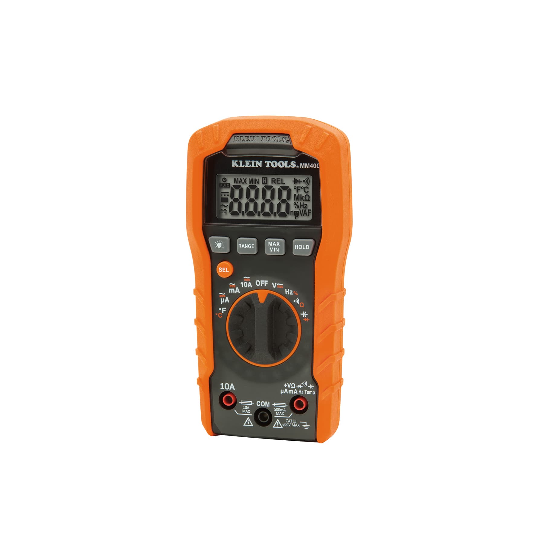
Auto-ranging, CAT III 600V. Aimed at tradespeople and home electrical work.
As an Amazon Associate I earn from qualifying purchases. Prices and availability are shown on Amazon.
Frequently asked questions
What resistance should a motor winding read?
There is no universal value. Small motors often read a few ohms to tens of ohms per winding, while large industrial motors can read well under one ohm. The motor manufacturer or a rewind shop record may list it, but the most useful check is comparison: the three windings of a three-phase motor should read almost the same as each other.
What reading to ground means a motor is bad?
On a multimeter, any steady resistance reading between a winding and the frame, rather than OL, points to a ground fault and the motor should not be run. A pass on the meter is not proof of good insulation, though. Insulation resistance is judged with an insulation tester at a suitable test voltage, against the minimum given by the manufacturer or the applicable standard.
Can I test a motor winding while it is still connected to the VFD?
Do not. The drive output stage sits across the motor leads, so resistance readings include it, and an insulation tester can damage the drive. A drive also holds charged DC bus capacitors after it is switched off. Isolate, wait the time the drive manual specifies, confirm zero volts, then disconnect the motor leads at the drive or terminal box before testing.
Why does a motor keep tripping when its windings test good?
The winding may have a turn-to-turn short or insulation weakness that a low-voltage meter cannot reveal, or the cause may be outside the motor: a seized bearing or overloaded machine, a lost supply phase, a failing starter contact or capacitor, or a wrongly set overload. Measure the running current on each phase with a clamp meter and compare it with the nameplate.
Is it worth rewinding a motor with a shorted winding?
It depends on size and type. Small fractional-horsepower motors are usually cheaper to replace than to rewind, while larger industrial motors are commonly sent to a rewind shop, which also tests the insulation and checks the bearings. Get a repair quote alongside the cost of a new motor, weigh the lead time and downtime, and consider whether a newer replacement would run more efficiently over its working life.

