HOW-TO GUIDE
How to Test a Diode With a Multimeter
By the OhmSavvy Research Team ·

Power off and discharge before you probe
- Diode mode is for unpowered parts only. Unplug the device and remove its battery first.
- Rectifier diodes in mains power supplies sit next to large filter capacitors that can hold a dangerous charge after unplugging. Confirm they read near 0V on the DC volts range before touching anything.
- Any voltage left on the board corrupts the reading and can damage the meter's diode circuit.
Why not just use resistance mode?
A diode only conducts current in one direction, which makes it behave unpredictably under a standard resistance measurement — some meters' internal ohmmeter current can still turn a diode on, giving an inconsistent, hard-to-interpret reading that varies by meter model. Diode mode avoids this entirely by applying a known, controlled forward current and directly reporting the voltage dropped across the junction — a number that actually means something consistent across different meters.
How diode mode actually works
In diode mode, the meter pushes a small test current through the probes and displays the voltage drop across whatever's connected, in volts rather than ohms. A diode oriented for forward conduction drops a predictable amount of voltage (roughly 0.5-0.7V for silicon); a diode oriented for reverse blocking shows an open-circuit ("OL") reading, since current can't flow backward through a healthy junction.
1Check the leads and find the band
Set the dial to diode test mode (the diode symbol) and touch the probe tips together. Most meters beep and show a value close to 0V; if yours shows OL, a lead or the meter's fuse path is the problem, not the diode. Then find the cathode: on glass and black-epoxy diodes it's the end with the painted band, and on surface-mount parts it's usually a stripe or notch on one end of the case.
2Read the forward drop
Touch the red probe to the anode and the black probe to the band end. Hold steady contact for a second or two and write the number down. A 1N4148 signal diode or a 1N4007 rectifier typically lands somewhere around 0.5–0.7V; a big power rectifier can read a little lower because its larger junction passes the small test current more easily.
3Reverse the probes
Swap the leads so red is on the band. A good diode blocks, and the meter shows OL. Any number at all in this direction is a warning sign: a few hundred millivolts suggests a short, and a reading that slowly creeps downward usually means you're charging a capacitor somewhere else in the circuit rather than looking at the diode alone.
Reading the results
| Forward reading | Reverse reading | Likely condition |
|---|---|---|
| ~0.5–0.7V (silicon) or ~0.2–0.4V (Schottky/Ge) | OL (open) | Healthy diode |
| OL (open) | OL (open) | Open/failed diode — no conduction either way |
| Low voltage or beep | Low voltage or beep | Shorted diode — conducts both ways |
| Unexpectedly low, below typical range | OL | Possibly a different diode type (Schottky/Ge) — check the datasheet before assuming a fault |
Typical forward drops by diode type
The number on the display is the most useful clue you have, so it helps to know roughly where each family sits. These are typical textbook values at a small test current, not limits; the exact figure depends on the part, its temperature and how much current your meter pushes.
Notice the LED bars. A meter can only show a forward drop smaller than the voltage its diode range applies, and many handheld meters apply only around 2–3V. A blue or white LED can therefore read OL in both directions on some meters even though it's perfectly healthy. Before you bin an LED on that basis, check your meter manual's diode-test voltage or try a coin cell and a resistor instead.
4Testing an LED the same way
LEDs are diodes, so the same test applies, with one bonus: many meters' diode-test current is enough to make the LED visibly glow when oriented for forward conduction. That glow confirms polarity and that the LED isn't open or shorted, without needing an external power supply to light it.
The in-circuit caveat
Bridge rectifiers are just four diodes in one package, so the same forward-and-reverse routine applies to each pair of pins; our bridge rectifier guide maps out all eight probe positions. Zeners need a different approach for their breakdown voltage, covered in how to test a Zener diode, and if your readings look off for a part you know is good, see why a multimeter shows the wrong diode voltage.
Which meter to use
Any meter with a diode position on the dial will do this job; the differences are in display resolution, how firmly the leads seat, and whether the meter is safe to use on the mains side of the same equipment later. More options are in our best multimeters for electronics repair guide.
Meters from our reviews
Hands-on tested. True RMS, CAT III 600V, diode test and continuity on the dial.

Hands-on tested. Same body as the 117, adds capacitance and frequency, no NCV.
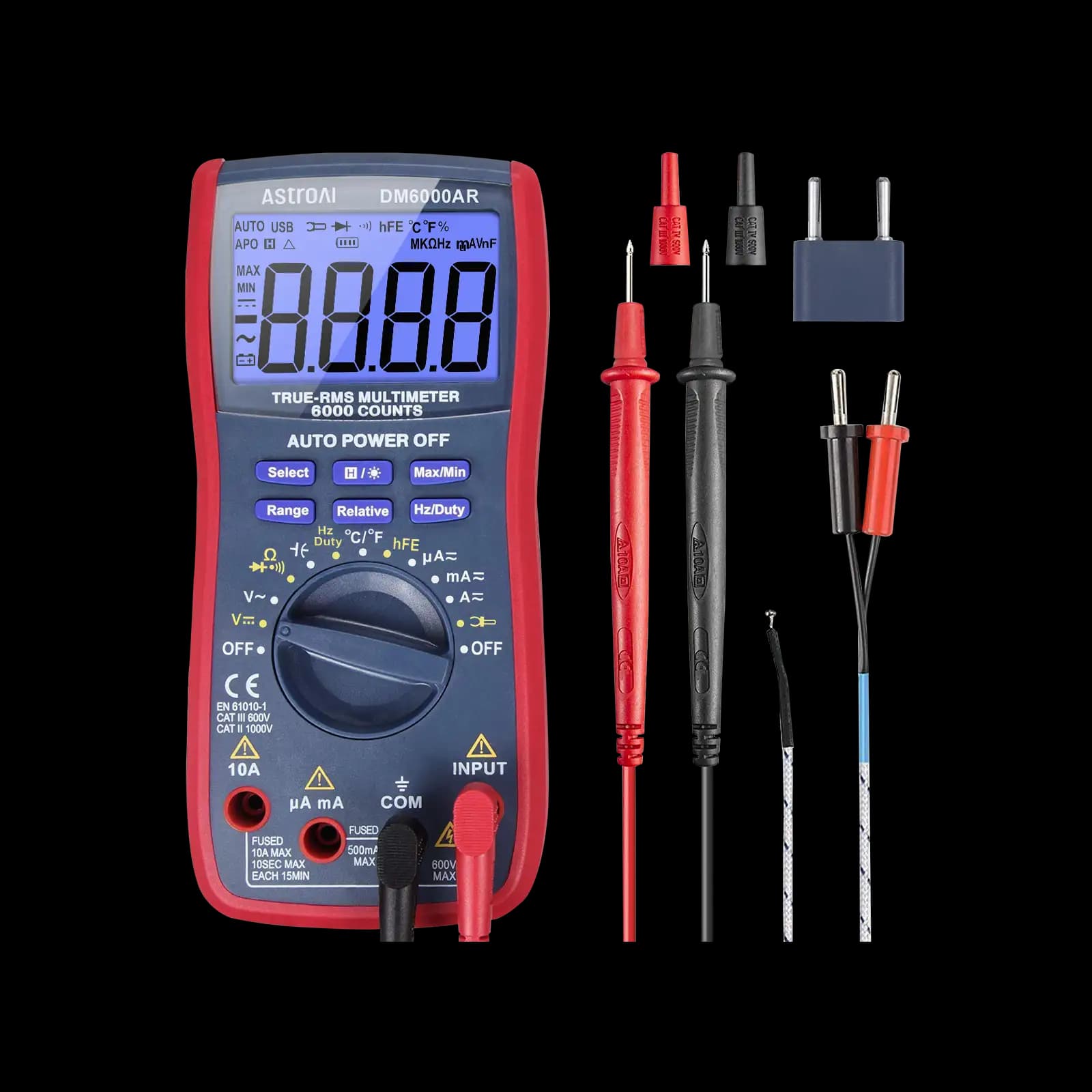
Budget 6,000-count True RMS meter for low-voltage bench work; no CAT rating stated.
As an Amazon Associate I earn from qualifying purchases. Prices and availability are shown on Amazon.
Frequently asked questions
What forward voltage should a healthy silicon diode show?
Typically around 0.5-0.7V in diode mode when the probes are oriented for forward conduction. Schottky diodes and germanium diodes read lower, often 0.2-0.4V. These are typical ranges, not strict limits — the exact figure varies by diode type and model, so compare against the part's datasheet for a precise spec.
Why does my LED glow faintly during a diode test?
That's expected and actually useful — many meters' diode-test current is enough to make an LED glow dimly when the probes are oriented correctly for forward conduction. It confirms both that the LED isn't open or shorted and which lead is which, without needing a separate power supply.
My diode reads the same low value in both directions — what does that mean?
That pattern indicates a shorted diode — one that conducts (or appears to conduct) in both directions instead of blocking in reverse. A healthy diode should show a clear forward voltage drop one way and an open (OL) reading the other way; a short in both directions means the junction has failed.
Can I test a diode while it's still soldered into a circuit?
Sometimes, but be cautious — other components in parallel with the diode can provide an alternate path for the test current, giving a misleading reading just like the parallel-resistance problem covered in our resistance guide. For a reliable reading, isolate the diode (lift one leg) whenever the in-circuit reading looks inconsistent with what you'd expect.
Can the forward voltage reading tell me what type of diode I'm holding?
It's a useful clue, not a certainty. Roughly 0.5-0.7V points to an ordinary silicon rectifier or signal diode, 0.2-0.4V points to a Schottky diode or germanium diode, and Zener diodes read close to an ordinary silicon diode's forward value in this direction (their special reverse-breakdown behavior doesn't show up in a simple forward/reverse diode-mode check). Markings on the part itself are more reliable than voltage alone when you need to be sure of the exact type.

