HOW-TO GUIDE
How to Test a Solenoid Valve Coil Resistance With a Multimeter
By the OhmSavvy Research Team ·

Before you start
- Many valves in appliances, heating and industrial plant have mains-voltage coils. Switch off and isolate the supply, lock it off where you can, and confirm with the meter on AC volts that the coil terminals are dead before you touch them.
- The valve may hold water, air, steam or hydraulic pressure. A resistance test does not require opening the valve; do not dismantle it until the line is isolated and depressurised.
- Gas valves and valves on safety systems, such as boiler or burner gas controls, should be tested and replaced only by a qualified engineer.
1Isolate the valve and unplug the coil
With the power off, unplug the coil's connector or disconnect its two wires and note where they went. Measuring with the coil still wired in leaves the controller, a relay contact or other valves in parallel, which can pull the reading down. On industrial coils with a DIN-style plug, remove the plug and measure on the coil's own pins: the plug can contain an LED, a suppression part or a rectifier that confuses the reading.
2Work out the expected resistance
The coil's label or the manufacturer's data sheet usually gives its voltage and power. For a DC coil, current is limited only by the winding's resistance, so resistance follows closely from R = V² ÷ P: a 12 V, 10 W coil works out at 144 ÷ 10 = 14.4 Ω.
AC coils are different. Their inductance adds reactance, so the current is limited by impedance, not resistance alone, and the ohms you measure are lower than V² ÷ P suggests. AC coils are also often rated in VA, sometimes with separate inrush and holding figures. For an AC coil, treat V² ÷ VA as an upper limit rather than a target, and use the manufacturer's stated resistance where one is given.
| Coil rating | Calculation | Expected reading |
|---|---|---|
| 12 V DC, 10 W | 12² ÷ 10 = 144 ÷ 10 | ≈ 14.4 Ω |
| 12 V DC, 5 W | 144 ÷ 5 | ≈ 28.8 Ω |
| 24 V DC, 8 W | 576 ÷ 8 | ≈ 72 Ω |
| 24 V DC, 20 W | 576 ÷ 20 | ≈ 28.8 Ω |
| 24 V AC, 7 VA (holding) | 576 ÷ 7 ≈ 82.3 | Below ≈ 82 Ω (AC: lower) |
| 120 V AC, 10 VA | 14,400 ÷ 10 | Below ≈ 1,440 Ω (AC: lower) |
| 230 V AC, 8 VA | 52,900 ÷ 8 ≈ 6,612 | Below ≈ 6.6 kΩ (AC: lower) |
The same method is used for heating elements, which are almost purely resistive; our guide to measuring the resistance of a heating element works through more examples.
3Measure across the coil terminals
Set the meter to ohms, touch the probes together and note the lead resistance, which matters on low-ohm DC coils. Then hold the probes firmly on the two coil terminals without touching the metal with your fingers, since your body resistance in parallel can skew high readings. On a manual-ranging meter, pick the range just above the expected value. Give the reading a moment to settle: the inductance of a large coil can make the display creep before it stops. Wiggle the coil's lead-outs gently while you watch, too, because a winding that is broken where the fine wire meets its terminal may read correctly one moment and OL the next. The basics are covered in how to use a multimeter.
Allow for coil temperature
Solenoid windings are copper, and copper's resistance rises by roughly 0.39% for every degree Celsius. A coil that has been energised for a long time can be much warmer than the room, so measure it cold where possible, or expect a higher reading. Taking the 12 V, 10 W coil at 14.4 Ω at 20 °C:
The reverse also matters: a coil that reads correctly cold but stops working once warm may have a winding or joint that opens with heat. If you suspect that, measure again straight after the valve has failed in use, with the power isolated.
4Test for a short to the valve body
Set the meter to its highest ohms range. Put one probe on a clean, unpainted part of the valve body or the earth terminal, and the other on each coil terminal in turn. Both should read OL. Any reading at all means the winding insulation has broken down to the metalwork, which on a mains coil can trip the RCD or GFCI, or make the valve body live if the earth is faulty. If OL is unfamiliar, see what OL means on a multimeter.
A multimeter tests at a low voltage, so it only finds hard faults. Insulation that breaks down only at mains voltage needs an insulation resistance tester, which is how electricians check mains coils and motors.
Reading the results
| Reading | Likely meaning | Next step |
|---|---|---|
| Close to the expected value, body OL | Coil is probably good | Check supply voltage and mechanics |
| OL across the terminals | Open winding or broken lead | Replace the coil |
| Near 0 Ω, or far below expected | Shorted winding | Replace the coil and check the controller output |
| Somewhat low on a DC coil | Possible shorted turns, or a cold coil | Compare with a known-good coil |
| Any value from terminal to body | Insulation failure to metalwork | Replace the coil; do not re-energise |
| Different value each way round | Diode or rectifier in the coil or plug | Measure on the bare coil pins |
01
Isolate
Power off, prove dead
02
Unplug coil
Nothing in parallel
03
Expected Ω
V² ÷ P (DC)
04
Measure coil
Open, short or OK
05
Body test
Each terminal: OL
Good coil, valve still stuck?
Check the voltage that reaches the coil
A coil that passes the resistance tests cannot open the valve if its supply never arrives. On a low-voltage valve, reconnect the coil, set the meter to AC or DC volts to match the coil, and measure across the coil connector while the controller is calling for the valve to open. You should see close to the coil's rated voltage. Measure at the coil, not at the controller, so that a broken wire or corroded joint in between shows up as a missing voltage.
If the voltage is there and the coil is good, the problem is mechanical. If the voltage is missing, work back towards the controller: its output terminal, a relay or triac that drives the coil, a fuse, or the transformer feeding it. On mains-voltage valves, live voltage checks are work for someone trained and equipped for it; the meter must have a CAT rating suited to the circuit.
Some technicians also hold a steel screwdriver near an energised low-voltage coil to feel its magnetic pull. That confirms the coil is producing a field, but it says nothing about how strong the field is, so treat it as a quick hint rather than a test, and never do it on a mains coil.
Irrigation, appliance and industrial valves
Garden irrigation valves commonly use 24 V AC coils driven by a controller. A handy trick is to measure at the controller between a zone's station terminal and the common terminal, with both wires disconnected from the controller: a reading close to the coil's value means the coil and field wiring are intact, while OL points to a break in the cable or a failed coil. If none of the zones work, check the controller's supply; our guide to checking a 24 V transformer covers that.
Appliance inlet valves, such as those on washing machines and dishwashers, typically have mains-voltage AC coils that read in the kilohm range, and some have two or more coils in one body for different water paths. Test each coil separately, and unplug the appliance first.
Industrial valves come with coils for many voltages, AC and DC, often with a rating plate on the coil. Some AC-supplied coils have a rectifier built in and are really DC coils, so they read like a diode in one direction; the manufacturer's data sheet says which type you have.
Which meter to use for solenoid coils
Any digital meter with an ohms range can test a coil. Because many solenoid valves sit on mains circuits, choose a meter with a CAT rating suited to the installation for the voltage checks you make before and after. The meters below are from our best multimeters roundup.
Meters in our reviews
True RMS, auto-ranging, CAT III 600V. Best for electricians and serious hobbyists.
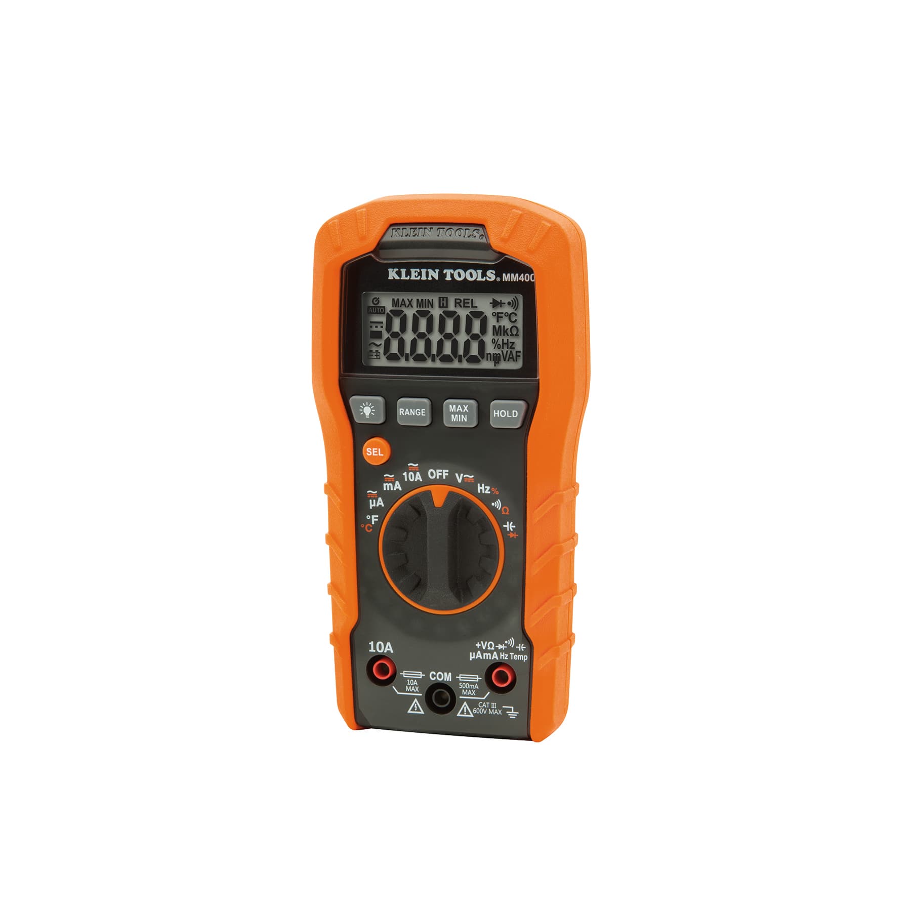
Auto-ranging, CAT III 600V. Best for tradespeople and home electrical work.

6,000-count display for coil ohms and True RMS for the AC supply to the coil. CAT III 1000V / CAT IV 600V.
As an Amazon Associate I earn from qualifying purchases. Prices and availability are shown on Amazon.
Frequently asked questions
What resistance should a 24 V irrigation valve solenoid have?
Many 24 V AC irrigation solenoids read in the tens of ohms, but the exact figure depends on the manufacturer and model, so look up the specification for yours. Because these are AC coils, the reading will be lower than the voltage squared divided by the VA rating. Compare a suspect valve with a known-good one of the same model if you can.
Can a solenoid coil test good but still fail?
Yes. A resistance test finds open windings and many shorts, but it cannot detect a few shorted turns that barely change the reading, or insulation that breaks down only at full voltage. If the coil reads correctly, also check that the supply voltage actually reaches the coil when the valve is told to open, and look for mechanical faults.
Does a solenoid coil have polarity?
A plain wound coil does not; it measures the same in either direction. Some DC coils and connectors include a suppression diode, an LED or a rectifier, and those do have polarity and can read differently when you swap the leads. Check the coil or connector markings and the manufacturer's wiring diagram before connecting power.
Can I test a solenoid coil without removing it from the valve?
Yes. The coil usually stays on the valve for a resistance test; you only need to disconnect its wires or unplug its connector so nothing else is in parallel. Removing the coil from its stem is useful for the body test on some designs, but never energize a coil while it is off the valve, because many coils can overheat that way.
Why does my solenoid valve coil get hot?
Many coils rated for continuous duty run warm to hot when energized for long periods, which is normal within the maker's rating. Excess heat points to a supply voltage above the coil rating, a coil of the wrong voltage or AC/DC type, or, on AC coils, a plunger that cannot seat fully and so keeps the current high. Discolored insulation or a burning smell means the coil should be replaced.

