HOW-TO GUIDE
How to Test a Car Ignition Coil With a Multimeter
By the OhmSavvy Research Team ·
High voltage: keep clear while the engine runs or cranks
- An ignition coil produces many thousands of volts at the secondary output. Never touch the coil tower, plug wires or boot while the engine is running or cranking, and never hold a lead against them by hand.
- Do all resistance checks with the ignition off and the coil connector unplugged. Applying an ohmmeter to a powered circuit gives false readings and can damage the meter.
- Don't crank the engine with a coil output disconnected and ungrounded. The spark seeks another path, which can damage the coil, the engine computer or you. Use a proper spark tester.
- If you have a pacemaker or other implanted medical device, leave running ignition tests to someone else. Hybrid vehicles also carry high-voltage battery circuits; leave orange cables alone and use a qualified mechanic for anything near them.
Symptoms and causes
A coil test usually starts with a misfire code that names one cylinder, a stumble under acceleration, or a misfire that only appears once the engine is hot. The table maps each complaint to the check that confirms it.
| Symptom | Likely cause | How to check | Fix or who to call |
|---|---|---|---|
| Misfire code on one cylinder | Failed coil, plug or boot on that cylinder | Swap the coil to another cylinder; see if the code follows | Replace the coil (and check the plug) |
| Dead cylinder, coil reads OL | Open primary or secondary winding | Ohms across each winding, connector unplugged | Replace the coil |
| Misfire only under load or when hot | Insulation breaking down at high voltage | Spark tester at the rated gap; swap test | Replace the coil; check for oil in the plug well |
| Several cylinders misfire at once | Shared coil feed, fuse, relay or ground | DC volts and ground at each coil connector | Repair the feed or ground |
| No spark on any cylinder | Coil feed, crank sensor or engine computer | Feed volts at the coil; crank sensor signal | Mechanic or auto electrician if the feed is good |
| Coil passes every meter test, misfire remains | Plug, boot, injector or compression | Plug inspection; injector test; compression test | Work through the other causes or see a mechanic |
1Identify the coil type
Before reaching for the meter, look at how many pins the coil connector has and where the high-voltage output goes. That tells you which of these tests you can actually do:
Canister coil
Older single coil feeding a distributor. Primary and secondary are both reachable; the classic resistance test applies.
Coil pack (waste spark)
One coil fires two cylinders at once. Primary pins on the connector, secondary between the paired towers.
Coil-on-plug, two pins
Sits on each plug, driven by the engine computer. Primary is usually measurable; secondary may be.
Coil-on-plug, 3-4 pins
Driver electronics built in. Resistance tests are not meaningful; check power and ground instead.
How the two windings work
A coil is a step-up transformer. The primary has relatively few turns of thicker wire; the secondary has a great many turns of very fine wire. When the driver switches off the primary current, the collapsing magnetic field induces a much higher voltage in the secondary, enough to jump the plug gap. That construction explains the readings you should expect: low resistance on the primary, far higher on the secondary.
The numbers behind a spark
Typical ranges help you recognize a reading that is wildly wrong, but they vary between designs, so the service manual always wins. As a broad guide, coil-on-plug primaries often read somewhere around 0.3 to 1 Ω, older canister primaries around 0.5 to 2 Ω, and secondaries commonly several thousand ohms, often somewhere in the 5 to 15 kΩ region. The chart puts illustrative values on a log scale, because the secondary is roughly ten thousand times the primary.
Bars use a logarithmic scale: each step is ten times the last.
A low primary resistance does not mean a huge current, because the winding's inductance makes current build up gradually while the driver holds it on, a period called dwell. Take an illustrative primary of 0.6 Ω and 3 mH on a 14 V running supply. Current could eventually reach 14 ÷ 0.6 ≈ 23 A, but it rises with a time constant of L ÷ R = 0.003 ÷ 0.6 = 5 ms. After a 2 ms dwell it has reached 23.3 × (1 − e−0.4) ≈ 23.3 × 0.33 ≈ 7.7 A. The energy stored is ½ × L × I² = 0.5 × 0.003 × 7.7² ≈ 0.089 J, about 89 mJ, and that is what the spark spends.
The same picture explains two meter readings. Shorted primary turns lower both resistance and inductance, so current rises faster and the driver works harder. And a secondary that reads correctly can still fail, because the spark may need many kilovolts to jump a worn plug gap, and an ohmmeter applies only a volt or so. Measuring resistance proves the copper is continuous; it says nothing about the insulation at full voltage.
2Measure primary resistance
With the ignition off, unplug the coil connector. Set the meter to its lowest ohms range, touch the probe tips together and note the reading, or use the relative function to zero it. Then probe the two primary terminals: positive feed and the driver or negative side. A typical primary reads under a few ohms, so lead resistance is a meaningful share of the result: 0.2 Ω of lead on a 0.6 Ω coil inflates the reading by a third. Our guide to measuring resistance with a digital multimeter explains ranges and lead compensation if this is new.
3Measure secondary resistance
Move to a kilohm range and probe from the high-voltage output to the secondary return. On a canister coil that is usually the center tower to one of the primary terminals; on a waste-spark pack it is between the two towers of a pair; on a two-pin coil-on-plug, from the spring inside the boot to the terminal the manual names. Some coil designs include a diode in the secondary that blocks an ordinary ohmmeter, so follow the manual's probe points. Finally, check from each winding to the coil body or mounting bracket, which should read OL.
| Result | Likely meaning |
|---|---|
| Within the manual's range on both windings | Windings intact; move on to power, ground and dynamic tests |
| OL or infinite on either winding | Open winding or broken internal connection |
| Well below the specified range | Shorted turns inside the winding |
| Any continuity from a winding to the coil body or bracket | Insulation breakdown; replace the coil |
4Check power and ground at the plug
A coil that tests well but gets no supply will still produce no spark. With the connector unplugged and the ignition switched on, measure DC volts from the feed pin to a clean ground; it should be close to battery voltage, typically about 12.4 to 12.6 V with the engine off. A feed that reads a volt or more low points to a corroded fuse terminal or connector. Check the ground pin for continuity to the engine or battery negative, or better, a voltage drop test while cranking. On three- and four-pin coils this is the main meter test available. The trigger signal from the engine computer is a fast pulse that a meter can't display properly; that is a job for a scope or a dedicated ignition tester. If no coil gets a trigger at all, the crankshaft position sensor is a common culprit.
5Confirm with a dynamic test
Resistance measures the copper, not the insulation under the stress of tens of kilovolts. A coil with a hairline crack in its casing or breaking-down internal insulation can read perfectly and still misfire when hot, under acceleration or in damp weather. Resistance tests are also less useful on coils with integrated drivers, as above, and the coil itself often isn't designed to be serviced. The same open/short/in-range logic applies to other wound parts, as in our guide to testing a solenoid coil. If the coil, plug and wiring all pass and the misfire stays, check the fuel side with our fuel injector test or have a mechanic run a compression test.
Dynamic tests that confirm a suspect coil
Meters for this job
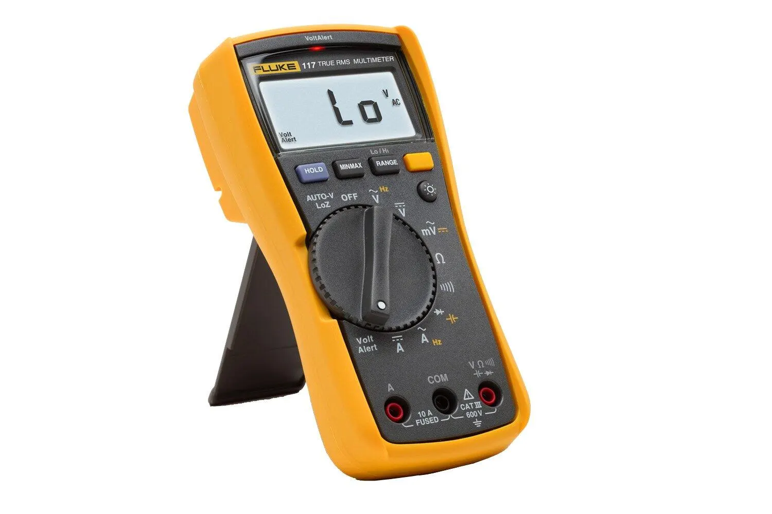
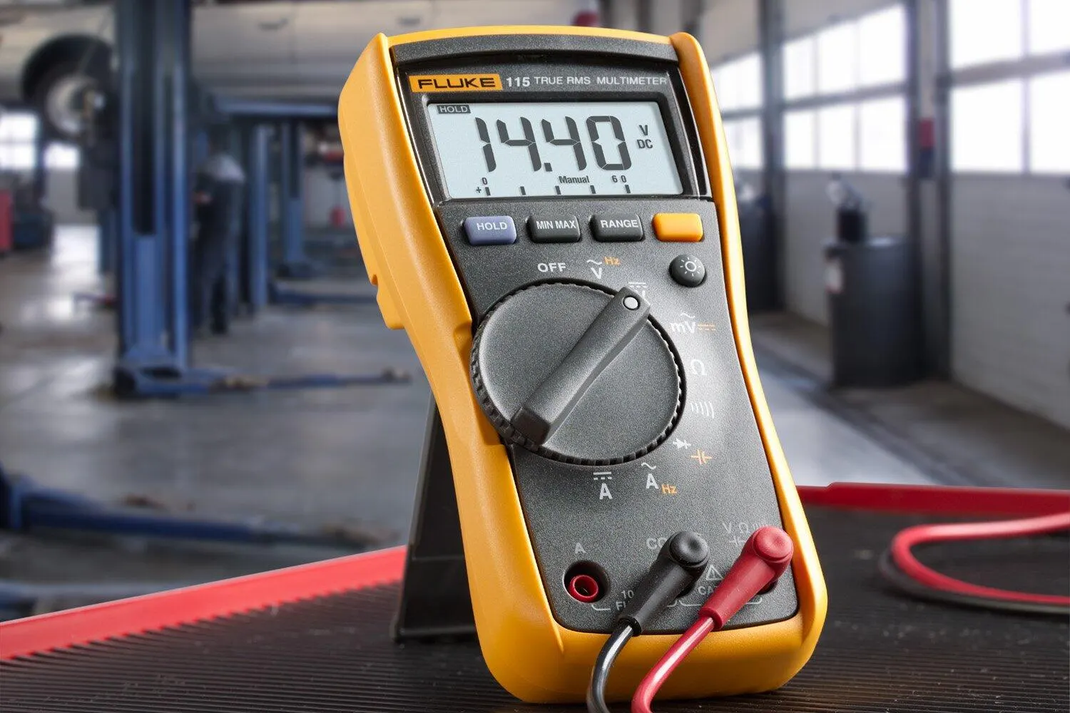
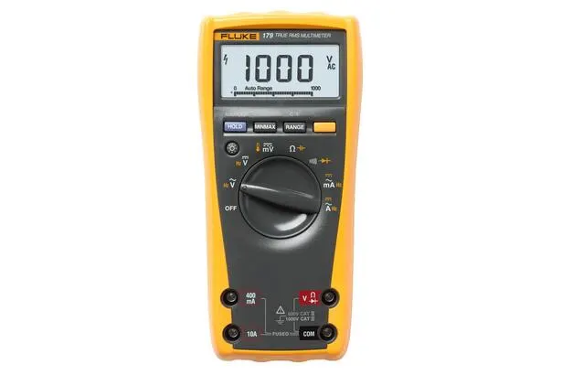
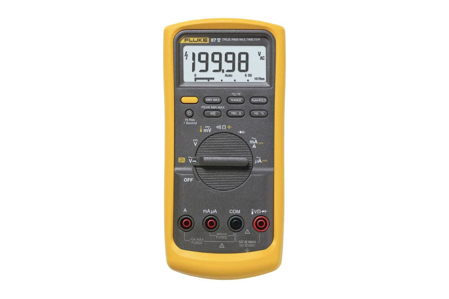
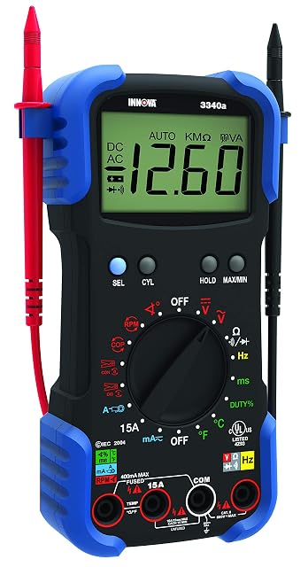
Primary readings under an ohm reward a meter with good low-ohm resolution and a relative mode; an inductive RPM pickup adds a quick check that each coil is firing. These picks come from our verified multimeter list.
Meters for coil resistance and ignition checks
True RMS, CAT IV 600V, with a 19,999-count high-resolution mode and an analog bar graph. Hands-on Tested.
RPM to 10,000 with the included inductive clamp (conventional, DIS and coil-on-plug), plus dwell. CAT II 600V.
As an Amazon Associate I earn from qualifying purchases. Prices and availability are shown on Amazon.
Frequently asked questions
How do you check ignition coil resistance?
Unplug the coil, set the multimeter to ohms, and measure across the primary terminals, then across the secondary (or the secondary terminal to the tower on a can-style coil). Compare both readings to the service manual's range for that coil — primary is typically under a few ohms, secondary typically several thousand. On coil-on-plug units with a built-in driver, there's often no primary winding to reach this way; check supply voltage and ground at the connector instead.
What resistance should an ignition coil have?
It depends on the coil. As a general pattern, the primary winding reads low, often under a couple of ohms, and the secondary reads much higher, usually several thousand ohms. The service manual or coil maker gives the actual range for your part and the temperature it applies at, and that figure is the one to compare against, not a generic chart.
Can I test a coil-on-plug coil with a multimeter?
Only partly. Many coil-on-plug units have the driver transistor built in and a three- or four-pin connector, so there is no direct path to the primary winding to measure. On those you can check supply voltage and ground at the harness plug, but judging the coil itself takes a spark tester, a swap test or a scope.
Will a bad ignition coil always set a check engine light?
Not always. A coil that fails completely usually causes a misfire the engine computer detects and logs, but an intermittent coil may only misfire under load or when hot, and the misfire may not be frequent enough to set a code straight away. A scan tool's misfire counters can help spot it before the light comes on.
Should I measure the coil hot or cold?
Resistance specifications are usually quoted at a stated temperature, often room temperature, and copper winding resistance rises by roughly 0.4% per degree Celsius as it heats. Measure at the temperature the manual specifies. If a coil only misbehaves when hot, testing it cold and again after a drive can reveal a change, though a dynamic test is more conclusive.
What are the symptoms of a bad ignition coil?
The common signs are a misfire you can feel as a stumble or shake, especially under acceleration or load, a rough idle, a flashing check engine light, a misfire code naming one cylinder, poorer fuel economy and, if the coil fails completely, a dead cylinder. A failing coil can also damage the catalytic converter, so do not keep driving with a flashing light.
Can a bad spark plug make an ignition coil fail?
Yes. A worn plug with a wide gap needs more voltage to fire, which pushes the coil's secondary harder on every spark and stresses its insulation. Oil or water in the plug well can also track high voltage down the outside of the boot. When you replace a failed coil, check the plug gap and condition and fix any oil leak into the well.