HOW-TO GUIDE
How to Test a Boiler Thermostat With a Multimeter
By the OhmSavvy Research Team ·

Isolate first: room stats switch 230V
- Most wired UK room thermostats carry mains voltage. Switch off and remove the fuse at the heating system's fused spur, then prove the terminals dead with a voltage tester you have checked on a known live source.
- Never open the boiler casing. Its internal thermostat, sensors and controls are Gas Safe engineer territory, and so is anything to do with the gas valve or flue.
- Continuity and resistance tests must only be done with the circuit dead.
Which thermostat are you testing?
"Boiler thermostat" can mean three different parts. Only the first two are things a householder should put a meter on:
Wired room stat
On the wall, switches the 230V call for heat. Mechanical dial or digital. The focus of this guide.
Wireless stat + receiver
Battery stat on the wall, receiver box near the boiler holds the relay. Test the receiver output.
Boiler's own stat/sensors
Inside the casing: flow temperature control and NTC sensors. Gas Safe engineer only.
A thermostat is a switch. In the usual layout it sits in a loop: a permanent live runs out from the boiler or wiring center to the stat, and when the room is colder than the setpoint the stat closes and sends that live back as the "switched live" that tells the boiler to fire.
1Isolate the heating circuit and prove it dead
Find the fused connection unit (spur) that supplies the boiler and controls, usually next to the boiler or the hot water cylinder. Switch it off and take the fuse out so nobody can restore power while you work. Some systems also have a separate spur for a wiring center or pump, so check the system isn't fed from two places.
Unscrew the thermostat from its backplate (usually one screw underneath) and prove every terminal dead with a voltage indicator or your meter on AC volts, testing between each terminal and earth and between each pair.
2Find the common and call-for-heat terminals
Before disconnecting anything, photograph the wiring. You only need to identify two terminals: the common that receives the live, and the output that goes live on demand. Typical markings:
| Stat type | Common / live in | Call for heat | Other terminals |
|---|---|---|---|
| Mechanical dial (many UK brands) | 1 | 3 | 2 = satisfied, N = accelerator neutral |
| Digital, relay output | COM or C | NO (normally open) | NC, L and N for power |
| Programmable stat replacing a timer | L or COM | CH ON or 3 | HW ON/OFF on combined units |
These are common patterns, not a rule. The diagram printed in the backplate or the manual is the authority for your model.
3Continuity test as you change the setpoint
Set the meter to continuity (or the lowest Ω range). Many stats are designed to be tested on the backplate terminals with the stat body clipped back on; on others the contacts are in the stat body itself. Either way, the circuit stays dead.
- Put one probe on common and the other on call for heat.
- Turn the setpoint well above room temperature. You should hear a click and get a beep or a reading under about 1 Ω.
- Turn it well below room temperature. The beep stops and the meter shows OL.
- Repeat a few times. Each change should switch cleanly, with no flickering reading.
Mechanical stats have a dead band
Optional: a live voltage check (competent persons only)
An electrician may instead restore power and measure AC volts from the call-for-heat terminal to neutral: around 230V when calling for heat and close to 0V when satisfied. That proves the whole chain to the stat including the programmer output, but it means working on live terminals. If you aren't trained and equipped for live testing, stick to the dead continuity test above. Your meter must be rated at least CAT II 300V for this, and preferably CAT III.
Wireless and low-voltage thermostats
With a wireless stat, the battery unit on the wall has no output terminals to test. The switching happens in the receiver near the boiler, which usually has a status LED and a manual override button. Isolated, its COM and NO terminals can be checked for continuity just like a wired stat, using the receiver's own manual test or override to switch the relay.
Some modern stats talk to the boiler over a low-voltage two-wire bus such as OpenTherm. These carry a data signal, not a simple switch, so a continuity test proves nothing. Check the wiring for continuity and let the boiler's own diagnostics, or an engineer, do the rest.
Reading the results
| What you see | Likely meaning |
|---|---|
| Beep on heat demand, OL when turned down | Thermostat is switching correctly |
| OL whatever the setting | Burnt or open contact, failed relay, or flat batteries in a digital stat |
| Beep whatever the setting | Welded contacts or stuck relay: boiler would run non-stop |
| Reading that flickers or sits at several ohms | Pitted contacts: likely to fail intermittently |
| Stat fine, but no live reaches common | Fault upstream: programmer, wiring center or fuse |
01
Programmer on?
CH set to ON
02
Stat switching?
COM to call-for-heat
03
Wiring intact?
Continuity to boiler
04
Zone valve?
On S-plan/Y-plan
05
Boiler fault
Call Gas Safe
When the thermostat tests fine
If the stat switches cleanly, check the cable back to the boiler or wiring center for a broken core using the method in how to test electrical wires. On systems with a hot water cylinder, a sticking motorised zone valve can stop the boiler firing even with a good stat. Beyond that, a boiler showing a fault code or locking out needs a Gas Safe registered engineer.
Which multimeter you need
Any meter with a continuity beeper handles the dead test. For live checks on 230V heating controls, choose a meter rated at least CAT III with well-shrouded leads. Compare options in our best multimeter for home use guide.
Meters in our reviews
True RMS, CAT II 600V, auto-ranging. Our budget pick for home use and beginners.
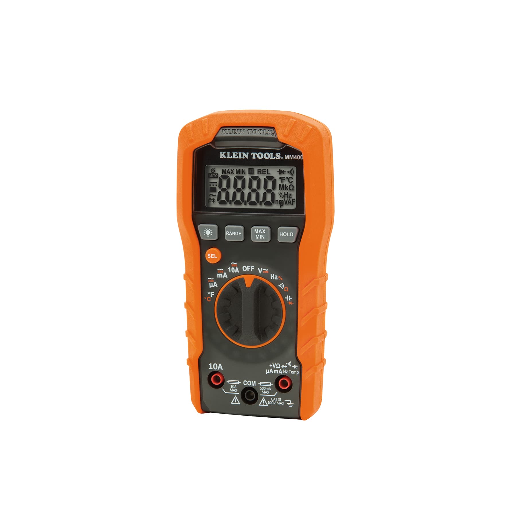
Auto-ranging, CAT III 600V, with temperature and capacitance. Not True RMS; discontinued by Klein.

True RMS, CAT III 600V Fluke field-service meter. Hands-on tested by OhmSavvy.
As an Amazon Associate I earn from qualifying purchases. Prices and availability are shown on Amazon.
Frequently asked questions
Can I test the thermostat inside my combi boiler myself?
No. The boiler's own control thermostat and its NTC temperature sensors sit inside the sealed casing next to gas components. In the UK, work inside a gas appliance is for a Gas Safe registered engineer. You can test the external room thermostat, programmer output and wiring to it once the circuit is isolated.
Why does my room thermostat click but the boiler doesn't fire?
A click means the relay or bimetal contact is moving, but the contacts themselves can be burnt and fail to pass current. Check continuity across COM and call-for-heat with the stat demanding heat. If that reads near 0 Ω, the stat is switching and the fault is further along: the programmer, a zone valve, wiring or the boiler.
What are terminals 1, 2 and 3 on a room thermostat?
On many UK mechanical stats, 1 is the common (live in), 3 is the call-for-heat output, 2 is a satisfied or cooling output and N feeds an accelerator heater. Brands differ, and digital stats often use L, N, COM, NO and NC instead. Always read the label on the backplate or the installation manual before probing.
Do batteries matter when testing a digital thermostat?
Yes. Many battery-powered digital stats hold their relay in its last state or stop switching when batteries are low, and some show no obvious warning. Fit fresh batteries before you test, then repeat the continuity check. A stat that only works on new batteries simply needed them.
Is it legal to replace a room thermostat myself in England?
Like-for-like replacement of a room thermostat on an existing circuit is generally treated as minor electrical work, but it must still be done safely and to BS 7671. Altering circuits can fall under Part P notification. If you're unsure, use a registered electrician or heating engineer.


