HOW-TO GUIDE
How to Test a Zener Diode With a Digital Multimeter
By the OhmSavvy Research Team ·
Keep the test at low voltage
- Remove power before any diode-mode or resistance check, and discharge nearby capacitors in a power supply before you touch the board.
- For the bench test, use a current-limited bench supply or a battery, never a mains-derived source without isolation. Always include the series resistor: a zener connected straight across a supply will overheat and fail.
- Small zeners get hot if the resistor is too small. Check the power figures below before switching on.
What makes a zener different
In the forward direction a zener behaves like any silicon junction. The difference is in reverse: an ordinary rectifier blocks until it is damaged, while a zener is built to break down cleanly at a specified voltage (Vz) and hold close to it across a range of currents. Zeners serve as references, clamps and simple shunt regulators. Our general guide to testing a diode with a multimeter covers the forward and reverse diode-mode checks for rectifiers, LEDs and Schottkys. This page goes further and measures the zener voltage itself.
Vz
Zener (breakdown) voltage, the figure printed on the part, e.g. 5V1 = 5.1 V.
Izt
Test current at which the datasheet specifies Vz. Measure near it for a fair comparison.
Power
Common small glass zeners are 0.5 W; larger axial parts are 1 W or more.
1Do the diode-mode forward check
With the zener out of circuit, or with one leg lifted, select diode mode. Put the red probe on the anode and the black probe on the cathode (the end with the band). A healthy part typically shows around 0.6–0.7 V, the normal silicon forward drop at the meter's small test current. Swap the probes: the display should read OL for most zeners.
There is one exception. A low-voltage zener, say 2.4 V or 2.7 V, can break down at the meter's open-circuit test voltage and show a reading in reverse too. That is not a short: a shorted part reads close to zero both ways, usually with the continuity beeper sounding.
Why a multimeter can't show the zener voltage directly
Diode mode works by pushing a small, fixed current through the part and displaying the voltage that develops. The source inside the meter has a limited compliance voltage, commonly in the region of 2 to 3.5 V depending on the model, so it simply cannot reach the breakdown point of a 5.1 V or 12 V zener. The display reads OL because the meter has run out of voltage, not because the zener has failed.
Two tests, two questions
2Measure the breakdown voltage with a supply and resistor
Build the circuit below on a breadboard or with clip leads. The zener is connected in reverse: the cathode (band) goes toward the positive side through the series resistor, the anode goes to the negative. Set the meter to DC volts and put it directly across the zener.
- Choose a supply voltage a few volts above Vz, for example 12 V for a 5.1 V part.
- Calculate the resistor (next section) and fit the nearest standard value at or above it.
- Switch on and read the DC voltage across the zener once it settles.
- Optional: raise the supply a few volts. The zener voltage should barely move while the voltage across the resistor takes up the difference. That flat response is the zener working.
If you want the actual current, measure the voltage across the resistor and divide by its value, the method explained in measuring voltage across a resistor.
Sizing the series resistor: the maths
The resistor drops whatever voltage the zener doesn't, so by Ohm's law:
R = (Vsupply − Vz) ÷ Iz
For a 5.1 V zener on 12 V at 5 mA: (12 − 5.1) ÷ 0.005 = 1,380 Ω. A standard 1.5 kΩ gives about 4.6 mA. The resistor dissipates 6.9 V × 4.6 mA, roughly 32 mW, and the zener about 23 mW, both well inside a 0.25 W resistor and a 0.5 W zener. For a precise comparison, aim for the Izt in the datasheet; 1 W parts are often specified at tens of milliamps, so recheck both power figures if you raise the current.
| Zener | Supply | Target Iz | Calculated R | Standard R |
|---|---|---|---|---|
| 3.3 V | 9 V | 5 mA | 1,140 Ω | 1.2 kΩ |
| 5.1 V | 12 V | 5 mA | 1,380 Ω | 1.5 kΩ |
| 9.1 V | 15 V | 5 mA | 1,180 Ω | 1.2 kΩ |
| 12 V | 18 V | 5 mA | 1,200 Ω | 1.2 kΩ |
| 15 V | 24 V | 5 mA | 1,800 Ω | 1.8 kΩ |
These are worked examples at a modest test current suited to small zeners, not datasheet limits.
Good, shorted, open or drifted: reading the results
| What you see | What it usually means |
|---|---|
| ≈0.6–0.7 V forward, OL reverse; bench reading near Vz | Good zener |
| Near 0 V in both directions, beeper sounds | Shorted junction, a common failure after overload |
| OL in both directions; bench reading equals the supply | Open zener: no current flows, so no drop across R |
| Forward check passes but bench reading is well off Vz | Drifted part, wrong part fitted, or test current far from Izt |
| Bench reading creeps down as the part warms | Often normal for higher-voltage zeners; heavy drift suggests overheating or damage |
Judge closeness with your meter's accuracy in mind; our guide to multimeter accuracy for electronics repair explains how to read a ±(% + counts) spec.
Which multimeter you need to test a zener
Both tests need only diode mode and a DC volts range, which almost every digital meter has. A higher count display shows the zener voltage with more digits, which helps when comparing a reference zener against a tight tolerance. For basics on modes and probe sockets, start with how to use a multimeter.
Meters in our reviews
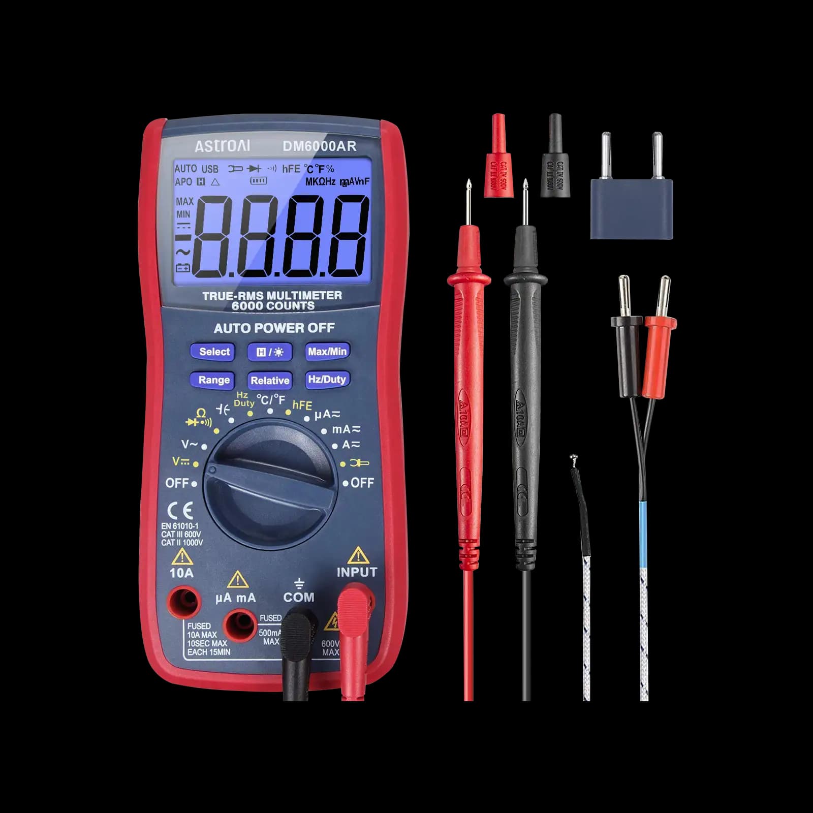
True RMS, 6,000-count, auto and manual ranging. Aimed at microcontroller and electronics projects.
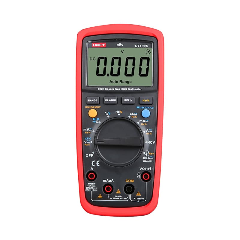
True RMS, 6,000-count, CAT III 600V, with both auto and manual ranging at a budget price.

6,000-count main display with a 19,999-count high-resolution mode, for finer voltage readings.
As an Amazon Associate I earn from qualifying purchases. Prices and availability are shown on Amazon.
Frequently asked questions
Can I test a zener diode in circuit?
Partly. With the board powered, you can measure the DC voltage across the zener and compare it with its rating: a regulator zener should sit close to its marked voltage. Unpowered diode-mode checks in circuit are less reliable, because parallel parts can make a good zener look shorted. If a reading looks wrong, lift one leg before condemning it.
How do I read the markings on a zener diode?
Small glass zeners are often printed with the voltage directly, such as 5V1 for 5.1 V or 12 for 12 V, sometimes with a series prefix like BZX55C. Others carry a part number, for example 1N4733A, which you look up in a datasheet to get the zener voltage and test current. The band always marks the cathode.
Can I use a 9V battery to test a zener diode?
Yes, for zeners rated a few volts below 9 V. A 9 V battery and a series resistor of around 1 kΩ make a simple test source for a 5.1 V zener, giving a few milliamps. It can't test zeners above roughly 7 V, because the battery needs headroom above the zener voltage to push current through the resistor.
Why does my zener read lower than its rated voltage?
Zener voltage depends on current. The rated figure is specified at a test current on the datasheet, and at much lower current the reading is usually somewhat below it, especially for zeners under about 6 V, which have a soft knee. Tolerance matters too: a 5% part can legitimately read a little high or low.
What is the difference between a zener and a regular diode test?
The forward check is the same: both read about 0.6-0.7 V in diode mode. A regular rectifier is only expected to block in reverse, so the test ends there. A zener is designed to conduct in reverse at a set voltage, so a complete test also measures that breakdown voltage with an external supply and resistor.


