HOW-TO GUIDE
How to Test a Bridge Rectifier With a Multimeter
By the OhmSavvy Research Team ·

Four diodes, one package
A standard full-wave bridge rectifier has two AC input terminals and two DC output terminals (+ and −), with four diodes internally arranged so that both halves of an AC cycle get directed the same way through the DC output. Testing the whole bridge means confirming each of those four diodes individually behaves like a healthy diode — conducting one way, blocking the other.
Identify the AC and DC pins
Most bridge rectifiers mark their pins directly on the case with ~ for the two AC inputs and + / − for the DC outputs. If yours isn't marked, look up the part number against its datasheet before testing — guessing risks misreading a perfectly healthy bridge as faulty.
The four diode tests
With the rectifier isolated from the circuit, diode mode selected, and following the standard internal layout shown above, these four probe combinations should each show a normal forward diode drop:
| Red probe | Black probe | Expected reading |
|---|---|---|
| AC1 | + | Forward drop (~0.4–0.7V) — diode D1 |
| AC2 | + | Forward drop (~0.4–0.7V) — diode D2 |
| − | AC1 | Forward drop (~0.4–0.7V) — diode D3 |
| − | AC2 | Forward drop (~0.4–0.7V) — diode D4 |
Reversing the probes on each of these four pairs should read OL (open), exactly as a single healthy diode would in reverse.
1Testing step by step
Set the meter to diode mode. Work through each of the four pin pairs above in turn, noting both the forward reading and its reversed (expected OL) counterpart. That's eight individual measurements covering all four internal diodes in both directions.
Interpreting the results
| What you see | Likely condition |
|---|---|
| All 4 forward readings normal, all 4 reverse readings OL | Healthy bridge rectifier |
| One pair reads OL in both directions | That diode has failed open — bridge needs replacing |
| One pair reads a low voltage or beep in both directions | That diode has failed shorted — bridge needs replacing |
| Forward readings are inconsistent or unusually low | Possible in-circuit interference — isolate the rectifier and retest |
The in-circuit caveat
Meters for rectifier testing
Any meter with a diode-test position will run the eight checks above. If the rectifier lives in a mains-powered supply, a meter with a proper CAT rating is the safer choice for the live voltage checks you will make before and after the repair.
Meters for diode and rectifier checks
Hands-on tested. True RMS and CAT III 600V for the live AC input and DC output checks around a power-supply bridge.

Hands-on tested. Same body and CAT III 600V rating as the 117, without NCV, plus capacitance for the smoothing cap.
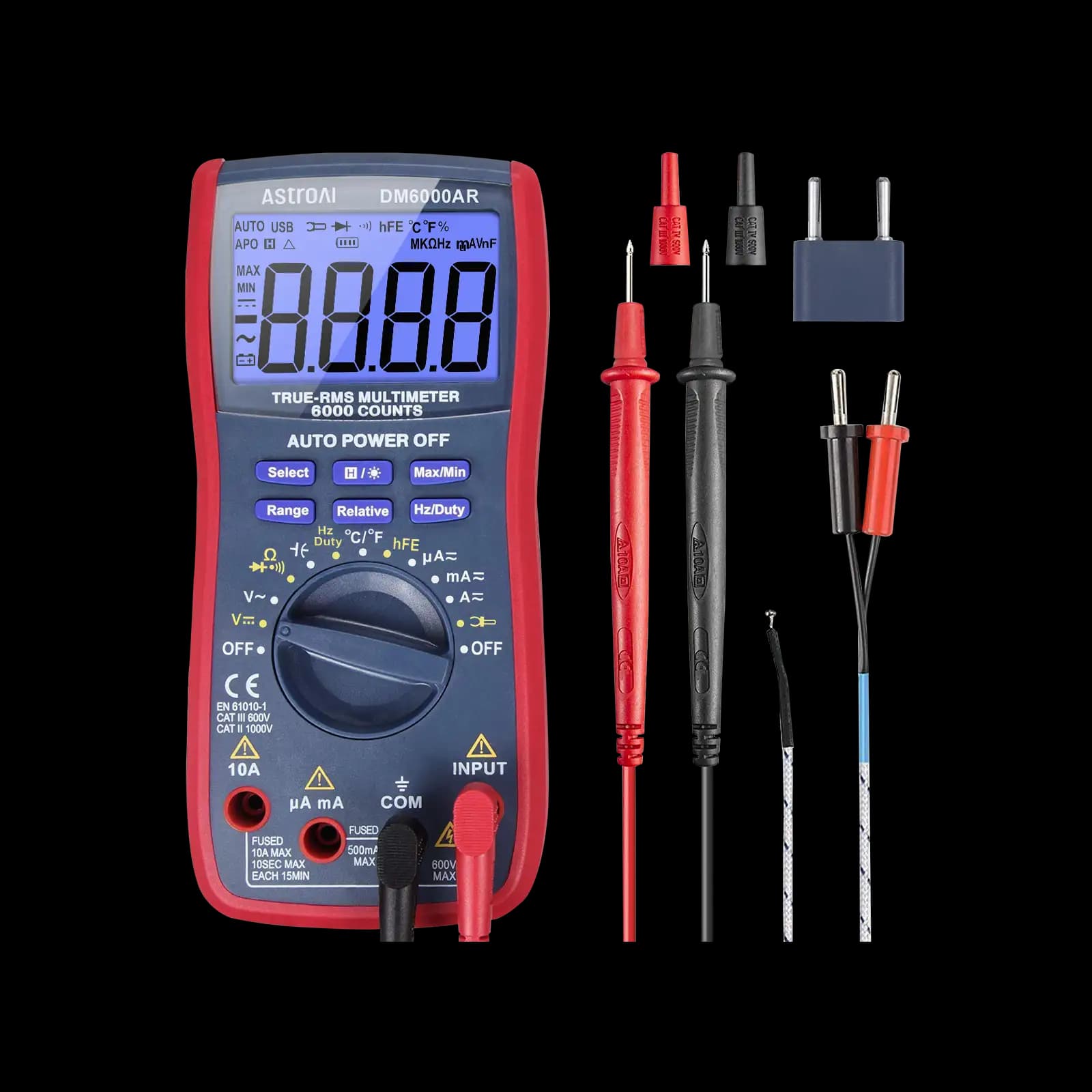
True RMS, 6,000-count bench meter for unpowered board work. No CAT rating stated, so keep it off mains.
As an Amazon Associate I earn from qualifying purchases. Prices and availability are shown on Amazon.
Frequently asked questions
What if the pins aren't labeled on the rectifier's case?
Many bridge rectifiers do mark the AC and DC pins directly on the case (symbols like ~, ~, +, −), but if yours isn't marked, check the part number against its datasheet for the pinout. Guessing at pin identity risks testing the wrong combinations and misreading a healthy bridge as faulty.
Can I test a bridge rectifier without removing it from the circuit?
Sometimes, but be cautious — exactly as with a single diode, other components connected in parallel with the bridge (especially a large smoothing capacitor across the DC output) can distort the reading. A capacitor in particular can hold a charge that interferes with diode-mode testing; discharge it safely first, or remove the rectifier for a clean, isolated test.
Is a bridge rectifier more likely to fail than a single diode?
Not inherently — it's still four individual diode junctions, each failing the same way a standalone diode would (open or shorted), usually from excessive reverse voltage, excessive forward current, or heat. A bridge module just packages that failure risk across four junctions instead of one.
Why do I get a reading on the AC-to-AC pins too?
Measuring between the two AC pins directly isn't one of the four standard diode tests, and the result depends on the specific internal diode paths in series — it's not a meaningful pass/fail check on its own. Stick to testing AC-to-+ and AC-to-− combinations as covered on this page.
Can a bridge rectifier pass a multimeter test and still be bad?
Yes. Diode mode pushes only a small test current at a couple of volts, so it can't show a junction that breaks down near its rated reverse voltage or one that fails only when hot. If the bridge tests fine but the supply still misbehaves, check the DC output ripple under load with a scope, or swap in a known-good part with the same voltage and current rating.
Where to go next
How to Test a Diode With a Multimeter →
The single-diode technique this page applies four times.
Why Does My Multimeter Show Negative Voltage? →
Why a rectifier's AC side naturally shows reversing sign as current direction alternates.
Check a Car Alternator Diode With a Multimeter →
The automotive-specific version of this test — a rectifier plate and diode trio inside the alternator.

