HOW-TO GUIDE
How to Test a Shunt Resistor With a Multimeter
By the OhmSavvy Research Team ·

Battery banks and solar arrays can deliver huge currents
- A 12 V or 48 V lithium or lead-acid bank can push hundreds of amps into a short. Remove rings and watches, use insulated tools, and never let a spanner bridge the shunt bolts to another terminal.
- Solar strings can sit at high DC voltage. Isolate the array before touching the charge controller wiring, and use a meter rated for the system voltage.
- Inverter and charger installations also carry 230 V (UK) or 120 V (North America) mains. Keep probes on the low-voltage side.
What a shunt resistor does
A current shunt is a deliberately tiny, precise resistance placed in series with a load. Because its value is known, the small voltage across it tells you the current: I = V/R. Battery monitors, solar charge controllers, e-bike controllers and analogue ammeters all work this way. It is usually a low-temperature-coefficient alloy such as manganin, either a bolted block with heavy terminals and small sense screws, or a strip or chip soldered to a board.
Why a normal resistance range can't measure a shunt
Short your probes together on the lowest ohms range and most meters show something like 0.1 to 0.5 Ω. That is the leads, the probe tips and the contact resistance at each touch point. A typical shunt is 0.1 to 10 mΩ, so it is buried well inside that figure, and the meter's finest step on the ohms range (often 0.1 Ω) is itself larger than the part. The ohms range is still worth a quick look, though: OL means the element or a joint is open. Our guide to what OL means on a multimeter explains that reading.
The four-wire (Kelvin) idea
Precision milliohm meters solve this with four wires. One pair forces a test current through the part; a second pair senses the voltage right at the element. Almost no current flows in the sense pair, so their resistance drops out of the result. Bolted shunts have this built in: big terminals for current, small screws for sensing. A bench supply and an ordinary multimeter can copy the idea.
1Test a shunt resistor with a known current
- Disconnect the shunt from the battery or circuit, or remove it if it is a separate block.
- Set a bench supply to constant current, for example 1 A, with a low voltage limit such as 2 V.
- Connect the supply leads to the heavy terminals, not to the sense screws.
- For an accurate current figure, put a second meter in series on its amps range; supply displays are approximate.
- Set the multimeter to DC millivolts and touch the probes to the sense screws, or to the inner ends of the element on a PCB shunt.
- Divide the voltage by the current. Swap probes to check polarity if the reading is negative.
Worked example: R = V / I
Reading shunt ratings such as 75 mV at a given amperage
Bolted shunts are labeled with two numbers: rated current and the drop at that current. 50 mV, 75 mV and 100 mV are common drops. Divide the drop by the current to get resistance, and use the ratio to turn any later millivolt reading into amps.
| Shunt label | Resistance | Drop at 1 A test | Amps per mV |
|---|---|---|---|
| 50 A / 75 mV | 1.5 mΩ | 1.5 mV | 0.667 A |
| 100 A / 75 mV | 0.75 mΩ | 0.75 mV | 1.333 A |
| 300 A / 50 mV | 0.167 mΩ | 0.167 mV | 6 A |
| 500 A / 50 mV | 0.1 mΩ | 0.1 mV | 10 A |
At 1 A, a 500 A shunt gives a tenth of a millivolt, so test big shunts at 10 A or more, or under a real load in circuit.
In-circuit checks: battery monitors, charge controllers and e-bikes
With the system running, apply a steady load, read the millivolts at the sense points, convert using the rating, and compare with what the monitor or controller reports.
- Battery monitors: the shunt sits in the main negative lead. Any negative wire that bypasses it makes the display read low with a healthy shunt.
- Solar charge controllers: the shunt is usually on the board. Compare reported charge current with the drop, and look for scorched solder nearby.
- E-bike controllers: the shunt is often a thick wire link of a few milliohms near the MOSFETs. Avoid the solder "shunt mod": it pushes current past what the motor and battery were designed for.
Probe the sense points directly; across the bolt heads the reading includes joint resistance. A bolt-to-cable drop larger than the shunt's own drop marks a loose or corroded joint. For the general technique of reading a drop and calculating current, see how to measure voltage across a resistor.
Heating and tolerance
Power in a shunt is I²R. A 10 mΩ shunt at 1 A dissipates only 10 mW, but a 0.75 mΩ shunt at 100 A dissipates 7.5 W. As the element warms its resistance shifts slightly, which is why makers commonly advise running bolted shunts continuously at no more than about two-thirds of rated current. Take test readings promptly, before the part heats.
Tolerance is printed on the label or datasheet, commonly somewhere between 0.1% and 5%. Your meter adds its own error on top: a reading of 10.0 mV on a 6,000-count meter resolves only to 0.1 mV, or 1%. A shunt within its stated tolerance plus the meter's accuracy is a pass.
Which multimeter works best for shunt testing
Resolution matters more than anything here, because the whole signal is a few millivolts. A meter with a dedicated mV range and a high-count display shows a 1% change clearly. Read multimeter accuracy for electronics repair to work out the real uncertainty, or start with how to use a multimeter if the mV and amps ranges are new to you.
Meters in our reviews
True RMS, 6,000-count display with a 19,999-count high-resolution mode, CAT III 1000V / CAT IV 600V.
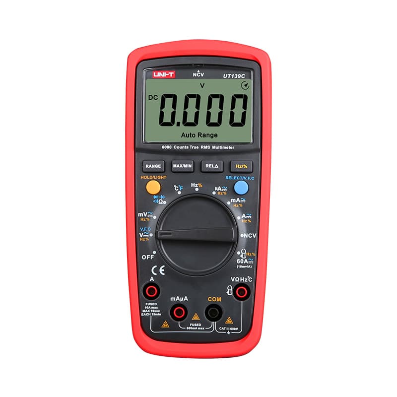
True RMS, 6,000-count, CAT III 600V, with both auto and manual ranging.
As an Amazon Associate I earn from qualifying purchases. Prices and availability are shown on Amazon.
Frequently asked questions
Can I measure a shunt resistor with the ohms setting on my multimeter?
Not usefully. A milliohm shunt is far smaller than the resistance of the test leads and probe contacts, which together often total a few tenths of an ohm. The display shows mostly lead and contact resistance, and the last digit is coarser than the shunt itself. Use the known-current method and calculate R = V/I instead.
What does 75 mV mean on a shunt?
It is the voltage drop the shunt produces at its full rated current. A 100 A, 75 mV shunt drops 75 mV when 100 A flows, so its resistance is 0.075 / 100, or 0.75 milliohms. Panel meters and battery monitors are calibrated to that pair of numbers, so both must match the shunt you fit.
How much current do I need to test a shunt?
Enough to produce a drop your meter resolves well, usually at least several millivolts. For a 10 mΩ shunt, 1 A gives 10 mV. For a 0.75 mΩ, 100 A shunt, 1 A gives only 0.75 mV, so 5 to 10 A from a capable supply or a real load gives a far more trustworthy result.
Can a shunt resistor go bad?
Yes, though the alloy element itself is robust. The usual faults are loose or corroded bolted joints, cracked solder on PCB shunts, and overheating that discolors or warps the element and shifts its value. A drop that rises over time at steady current, or a hot terminal, points to a connection problem before a failed element.
Why does my battery monitor read a different current from my clamp meter?
Check the shunt first: measure its millivolt drop under a steady load and calculate the current from its rating. If that agrees with the clamp, the monitor's settings or calibration are off. If it agrees with the monitor, the clamp may be misreading low DC current. Also confirm nothing bypasses the shunt on the negative side.


