HOW-TO GUIDE
How to Measure Ringing on a MOSFET Gate Signal With an Oscilloscope
By the OhmSavvy Research Team ·

Anatomy of a MOSFET gate waveform
Turning a MOSFET on is not a clean square edge at the gate. Vgs first climbs as the driver charges the gate-source capacitance, and the drain current starts to flow once Vgs passes the threshold. Then Vgs flattens into the Miller plateau while the drain voltage falls, because the driver's current is busy charging the gate-drain capacitance. When the drain has finished moving, Vgs rises again to the driver's final voltage. Ringing usually shows up at the sharp corners, especially at the end of the rise and the start of the fall.
Why the gate rings
The gate loop runs from the driver output, through the gate resistor and the trace to the gate, through the gate-source capacitance, and back from the source to the driver's ground. That loop has inductance from its traces and package leads, and with the gate capacitance it forms a resonant LC circuit. A fast driver edge excites it, and the gate resistor (plus the driver's own output resistance) is the only thing damping it. The wider the loop, the more inductance, the lower the ring frequency and the less damping a given resistor provides. The general theory of overshoot and ringing on any edge is in our overshoot and ringing guide.
The chart applies f = 1 ÷ (2π√LC) with an illustrative 2 nF of effective gate capacitance. Real values depend on the device and layout, but the pattern holds: ringing in the tens of megahertz is normal territory. A scope whose bandwidth is close to the ring frequency shows the ring smaller than it is; the Rigol DS1054Z, for example, lists 50MHz, so a 50 MHz ring would be noticeably attenuated on it.
1Probe a low-side gate from gate to source
What matters to the MOSFET is the voltage between its own gate and source pins. For a low-side device, whose source sits at or near ground, put the 10x probe tip on the gate pin and the short ground spring directly on the source pin. Do not use the long ground clip, and do not ground the probe to a convenient ground point elsewhere on the board: during fast switching, the source lead and the trace to ground carry a large di/dt, and the voltage across that inductance would be added to your reading. Our guide to connecting a probe correctly explains why a long ground lead rings by itself.
High-side gates need a differential or isolated probe
In a half-bridge or a high-side switch, the MOSFET's source is the switch node. It jumps between ground and the full supply voltage every cycle, often with fast edges. A standard probe ground on a bench scope is tied to mains earth, so clipping it to that source shorts the switch node to earth. To see a high-side Vgs you need a differential probe rated for the common-mode voltage and with good common-mode rejection at the switching speed, or an isolated measurement system designed for it.
Never float the scope
2Capture the switching edge
Set the channel to DC coupling and 10x, with the full bandwidth on: the 20 MHz limit that helps with rail ripple would hide most gate ringing. Choose a V/div that puts the full drive swing across about six divisions, leaving room above for the overshoot. Trigger on the gate channel, rising edge for turn-on or falling for turn-off, with the level around half the drive voltage, and use Normal mode. Then set the timebase so a few hundred nanoseconds around the edge fill the screen; at 50 ns/div individual ring cycles are easy to count. If a second channel is free, put it on the drain to see where the plateau lines up with the drain transition.
3Measure the ring frequency and peak Vgs
Stop the acquisition on a clear edge. Put one horizontal cursor on the final drive level and another at the highest point of the ring; the top cursor's absolute value is the peak Vgs to compare with the datasheet's absolute maximum. For the frequency, place vertical cursors on the same point of two ring peaks several cycles apart, divide the time by the number of cycles, and take the reciprocal. Repeat on the turn-off edge, where the concern is the opposite: how far the ring rises back toward the threshold while the device should be off, and how far it swings negative.
Compare with the device, not a rule
Damp the ringing: gate-drive fixes
Re-measure after each change, one at a time, so you know which one helped. Layout changes remove the cause; resistor and ferrite changes treat the symptom and cost switching speed.
| Fix | What it does | Trade-off |
|---|---|---|
| Raise the gate resistor | Adds damping to the gate LC loop | Slower edges, longer Miller plateau, more switching loss |
| Move the driver closer to the MOSFET | Shrinks loop inductance, raises and damps the ring | May need a board re-spin |
| Return the driver ground straight to the source pin | Keeps power current out of the gate loop | Needs care in layout; use a Kelvin source pin if the package has one |
| Ferrite bead in series with the gate | Adds loss at the ring frequency | Must be chosen for the ring frequency; can slow edges |
| Gate-source clamp (Zener or TVS) | Limits peak Vgs | Clamps the symptom only; adds capacitance |
| Separate turn-on and turn-off resistors | Tunes each edge on its own | One more resistor and a diode |
Troubleshooting gate ringing measurements
| Symptom | Likely cause | Fix |
|---|---|---|
| Ringing shrinks a lot with the ground spring | Probe ground-lead resonance | Keep the spring at the source pin |
| Ringing looks smaller than expected at full speed | Scope or probe bandwidth near the ring frequency | Turn off the 20 MHz limit; use more bandwidth |
| Large spikes that track the drain current | Probe grounded away from the source | Move the ground to the source pin itself |
| Gate rises again after turn-off | Drain dv/dt coupling through gate-drain capacitance | Lower turn-off gate resistance or add a negative off-bias |
| Scope trips the RCD or sparks on connection | Probe ground on a high-side or mains node | Disconnect and use a differential probe |
For the rest of a converter, including the switch node, our guide to switching power supply waveforms picks up where the gate leaves off.
Scopes with enough bandwidth for gate ringing
Pick the scope from the ring frequency you expect. Using the common rule of thumb that bandwidth should be several times the highest frequency you need to see, a gate ring in the 18 to 50 MHz range from the loop examples above points toward 100 MHz at minimum, and toward 200 MHz for the tightest, fastest loops. Two channels cover gate and drain; a four-channel scope adds the switch node and the driver input on the same capture.
Scopes for gate-drive work
Hands-on tested. 100MHz on 4 channels, so gate, drain, switch node and driver input fit at once.

200MHz on two channels, the most headroom here for fast rings on gate and drain.
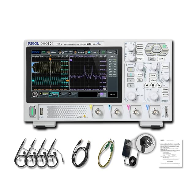
Hands-on tested. 12-bit resolution resolves small Vgs overshoot; its 70MHz limits fast rings.
As an Amazon Associate I earn from qualifying purchases. Prices and availability are shown on Amazon.
Frequently asked questions
Is the flat step in the middle of the gate rise a fault?
No. That is the Miller plateau. While the drain voltage swings, the gate current goes into charging the gate-drain capacitance, so Vgs pauses at a level set by the device's threshold and the load current. A plateau that is very long simply means the driver is supplying little current; ringing on top of it is what to investigate.
How much gate ringing is acceptable?
Two limits matter. The peak must stay well inside the gate-source absolute maximum in the datasheet, often ±20 V for standard parts and lower for many logic-level ones. And during the off state, ringing must never climb back toward the threshold voltage, which could turn the device partly on. A margin of a few volts from each limit is a sensible design target.
Will a bigger gate resistor always fix ringing?
It damps the gate loop, but it also slows switching, which raises switching loss and heat in the MOSFET, and it lengthens the Miller plateau. Treat it as a tuning knob alongside layout: shorten the loop first, then raise the resistor only as far as needed. Separate turn-on and turn-off resistors with a diode let you tune each edge independently.
Why does the ringing look worse with the standard ground clip?
The long ground lead and the probe input capacitance form their own resonant circuit, typically in the tens of megahertz, which is the same range as real gate ringing. Fast gate edges excite it. Switching to a short ground spring at the source pin removes most of that artefact, so whatever ringing is left belongs to the circuit.
Can I measure gate ringing with a multimeter?
No. A meter averages over far too long a time to show nanosecond events. A multimeter is useful for static checks on the device itself, such as a diode test across the body diode, but the gate waveform needs a scope.


