HOW-TO GUIDE
How to Test a Hall Effect Sensor With a Multimeter
By the OhmSavvy Research Team ·
Work safely around engines and harnesses
- Keep hands, hair and leads clear of belts and fans whenever an engine may be cranked. If you turn the engine by hand with the ignition on, pull the fuel pump or injection fuse first so it cannot start, and keep the transmission in park or neutral.
- Never feed a bench supply into a sensor still plugged into the vehicle module.
How a 3-wire Hall effect sensor works
A Hall effect sensor is a small chip whose sensing element produces a tiny voltage in a magnetic field, which on-board circuitry turns into a usable output. Because that circuitry needs power, most Hall sensors have three connections: a supply (often 5 V from a control module, sometimes 8 V or 12 V), a ground, and a signal output.
Outputs come in two broad styles. A digital sensor acts like a switch. Most are open-collector (or open-drain): they can only pull the signal low, so something else must pull it high. A linear (analogue) sensor gives a voltage proportional to the field, resting around half the supply with no magnet present.
Why a resistance test tells you nothing
Measuring resistance across the pins works for inductive pickups, which are just a coil of wire, but not for a Hall device. Between any two pins of a Hall IC the meter is probing transistor junctions and protection diodes, so the number changes with lead polarity and from one meter to the next.
Test the function, not the ohms
1Identify supply, ground and signal
On a vehicle, with the connector plugged in and the ignition on, back-probe each wire against a good ground: the supply reads the reference voltage, the ground reads close to 0 V, and the signal reads whatever the sensor is currently outputting. If the reference supply is missing, the fault is upstream of the sensor. Our guide to using a multimeter covers DC volts setup if you need a refresher.
To back-probe safely, slide a thin back-probe pin along the wire into the rear of the connector until it touches the terminal, keeping the weather seal intact. Never pierce the insulation, and take care not to bridge two terminals.
2Power the sensor from its circuit or a bench supply
In place, the module supplies power and normally the pull-up resistor too. On the bench, connect a current-limited supply at the sensor's rated voltage. For an open-collector output, add a pull-up resistor from the signal pin to the supply. A value around 10 kΩ is a common choice at 5 V; anything from roughly 4.7 kΩ to 10 kΩ suits typical outputs.
3Read the signal voltage while a magnet passes
Put the black lead on ground and the red lead on the signal, with the meter on DC volts. Bring a small magnet up to the sensing face, then take it away, and repeat a few times. For gear-tooth sensors, which contain their own biasing magnet, pass a steel object such as a screwdriver blade or a spanner across the tip instead. The output should switch cleanly between two levels each time.
Expected Hall sensor readings on a multimeter
| Sensor type | At rest | Field present | Likely fault if |
|---|---|---|---|
| Digital, open-collector (with pull-up) | Near supply, e.g. ≈ 5 V | Near 0 V, typically under 0.4 V | Stuck high or stuck low |
| Digital, push-pull output | Near 0 V or near supply | The opposite level | Never changes state |
| Linear / analogue | About half supply, ≈ 2.5 V at 5 V | Rises for one pole, falls for the other | Stuck at a rail, or no change |
These are typical values at a 5 V supply; exact levels vary by part. A reading stuck between the two digital levels usually means a missing pull-up, a poor ground, or the meter averaging a fast signal.
Testing crank, cam and bike speed Hall sensors
Automotive crankshaft and camshaft position sensors are a common place to meet Hall devices. With the connector back-probed and the ignition on, turn the engine slowly by hand using a socket on the crank pulley bolt: the signal should step between high and low as each tooth or window passes. While cranking, DC volts shows an in-between average, which still proves the signal is moving; a duty-cycle or frequency function shows it more directly. A sensor that looks fine but still triggers a code may be fed by a bad ground, so a voltage drop test on the car is worth doing on the sensor ground and reference wires.
On bicycles, many basic computer speed sensors are reed switches rather than Hall devices; those have two wires and test with continuity as the wheel magnet passes. E-bike speed and pedal sensors are often 3-wire Hall types fed with around 5 V from the controller and test as described above.
2-wire current-output Hall sensors
Some Hall sensors, including many active ABS wheel-speed sensors, have only two wires. Instead of switching a voltage, they switch between two current levels, commonly around 7 mA and 14 mA. Measure the current instead: put the meter on mA in series with the supply lead, or fit a small resistor in series (100 Ω turns those typical currents into about 0.7 V and 1.4 V) and read the voltage across it. Rotate the wheel slowly and the reading should alternate between the two levels.
Which multimeter to use for Hall sensor testing
Any digital meter with DC volts and a mA range covers these tests; duty-cycle or RPM functions help on running engines. Compare options in our best multimeters roundup.
Meters in our reviews
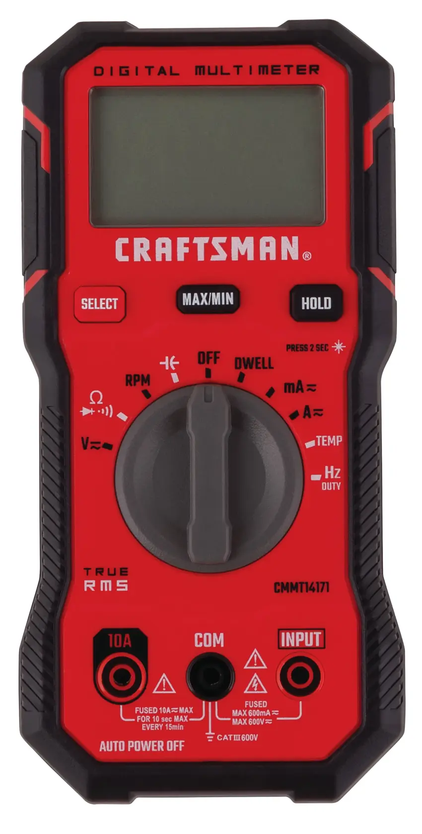
True RMS, CAT III 600V, with RPM, dwell and duty-cycle functions for automotive diagnostics.
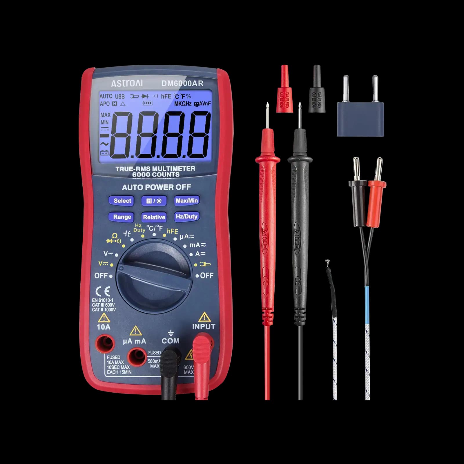
True RMS, 6,000-count, auto and manual ranging. Aimed at microcontroller and electronics projects.
As an Amazon Associate I earn from qualifying purchases. Prices and availability are shown on Amazon.
Frequently asked questions
Can I test a Hall effect sensor with an ohmmeter?
Not in any useful way. A Hall sensor contains an integrated circuit, so the resistance between its pins depends on the meter's test voltage, the lead polarity and the internal chip design. No datasheet lists a value to compare against. Power it and check the output voltage instead.
Why does my Hall sensor output read 0 V all the time?
If it is an open-collector type, it needs a pull-up resistor to the supply before it can show a high level. Without one, the output floats. Fit a pull-up of around 10 kΩ, or test it connected to its own module, which normally supplies the pull-up.
How do I tell a Hall crank sensor from an inductive one?
A Hall crank or cam sensor normally has three wires: a reference supply, a ground and a signal. An inductive (variable reluctance) sensor usually has two wires, makes its own AC voltage, and does have a measurable coil resistance. The wiring diagram confirms which type is fitted.
Does it matter which side of the magnet I use?
Often, yes. Many digital Hall switches respond to only one pole, so if nothing happens, flip the magnet over and try again. Latching types release only on the opposite pole. Linear sensors respond to both, with the output rising for one pole and falling for the other.
Can a multimeter catch an intermittent Hall sensor fault?
Sometimes. Watch the reading while you flex the harness, tap the sensor gently or warm it with a hair dryer, since many failures appear only when hot. A meter averages fast signals, though, so a sensor that drops the occasional pulse at speed may look fine. An oscilloscope or scan tool live data shows that kind of fault far better.



