HOW-TO GUIDE
How to Test a 3 Wire Proximity Sensor With a Multimeter
By the OhmSavvy Research Team ·

Lock out the machine before you reach in
- A sensor that suddenly switches can start a conveyor, press or cylinder. Follow your site's lockout/tagout procedure, isolate stored air and hydraulic energy, and keep hands clear of moving parts.
- Sensors run at 24 V DC, but the same panel usually carries 230 V (UK) or 120 V (North America) mains and often three-phase supply. Use a meter rated for the panel and never probe terminals you have not identified.
- Where possible, unplug the sensor and test it on the bench instead.
Inductive vs capacitive proximity sensors
Both types switch an electronic output when something comes close, with no physical contact. That makes them the non-contact cousin of the mechanical limit switch, and the reason you test them powered rather than with continuity.
Inductive
Senses metal only, using an oscillating magnetic field. Range is a few millimeters to a few tens of millimeters, rated for mild steel.
Capacitive
Senses metal, plastic, wood, liquids and granules through changes in capacitance. Usually has a sensitivity adjuster screw.
Flush vs non-flush
Flush (shielded) heads mount level with metal and sense a shorter distance. Non-flush heads reach further but need clear space around the face.
Brown, blue and black: the 3 wire proximity sensor colors
Most DC sensors follow the IEC color convention. Treat it as typical, not guaranteed: check the label or datasheet, especially on older or non-European parts.
| Wire (typical) | Function | M12 connector pin (typical) |
|---|---|---|
| Brown | Supply positive, +10 to +30 V DC | Pin 1 |
| Blue | Supply 0 V (negative) | Pin 3 |
| Black | Switched output | Pin 4 |
| White (4-wire types) | Second or complementary output | Pin 2 |
PNP (sourcing) vs NPN (sinking) outputs
The output is a transistor switch, and the type decides which way it switches. A PNP sensor sources current: when active, it connects the black wire to the positive supply, so the load sits between black and 0 V. An NPN sensor sinks current: when active, it connects black to 0 V, so the load sits between black and positive. Broadly, PNP is the norm in European machinery and NPN is common in Asian equipment, but both appear everywhere.
1Power the sensor at 10–30 V DC
Connect brown to the positive and blue to the negative of a DC supply inside the sensor's range; 24 V DC is the usual industrial control voltage. Then fit a resistor of roughly 2.2 to 4.7 kΩ, rated at least 0.5 W, as the load (PNP) or pull-up (NPN). At 24 V a 2.2 kΩ resistor draws about 11 mA, well under the typical output rating. Never connect the black output straight to a supply rail without a resistor: that is a short circuit when the output turns on.
2Measure the output with and without a target
Set the meter to DC volts. Put the black probe on blue (0 V) and the red probe on the black output wire. Read it with nothing in front of the sensor, then bring a steel target (a spanner works) up to the face, inside the rated distance.
An NPN sensor with a pull-up reverses this: close to 24 V with no target, falling to roughly 1 V or less when it switches. Without a pull-up, an NPN output usually reads near 0 V in both states, because nothing lifts the black wire while the transistor is off and the meter's own input ties it to 0 V. That is the most common reason a good NPN sensor gets condemned. If you need a refresher on DC voltage mode, see how to use a multimeter.
Quick sanity check on supply current
The status LED, sensing distance and NO vs NC
- Status LED: most sensors light an LED when the output is on. It is a useful first clue, but it only shows the sensor's internal state. A shorted or overloaded output can leave the LED lit with no voltage on the black wire.
- Sensing distance: slide the target in slowly and note where it switches. Much shorter than rated suggests a damaged face, swarf or the wrong target metal.
- NO vs NC: a normally open sensor turns its output on when a target arrives; a normally closed one turns it off. The part number or datasheet says which.
Testing a proximity sensor on the machine
In place, the PLC or relay input already provides the load. With the machine locked out except for the 24 V DC control supply (as your procedure allows), trigger the sensor by hand and measure at the input terminal against 0 V, then at the sensor connector. A signal at the sensor but not at the input means a cable or terminal fault; flexing cables on moving axes are frequent culprits.
Reading the result
| What you see | Likely meaning |
|---|---|
| Output swings fully with target; LED follows | Sensor is good; look at cable or controller |
| No supply voltage between brown and blue | Supply, fuse or wiring fault, not the sensor |
| LED changes but output never moves | Missing load or pull-up, or a failed output stage |
| Nothing changes, supply present | Dead sensor, or target material/distance out of range |
| Output stuck on with no target | Swarf on the face, nearby metal, or a shorted output |
| Switches only very close or intermittently | Damaged face, wrong target, or loose mounting |
A replacement must match the output type, NO or NC function, supply range, thread size and flush style.
Meters in our reviews for panel work
True RMS, CAT III 600V, non-contact voltage detection built in.
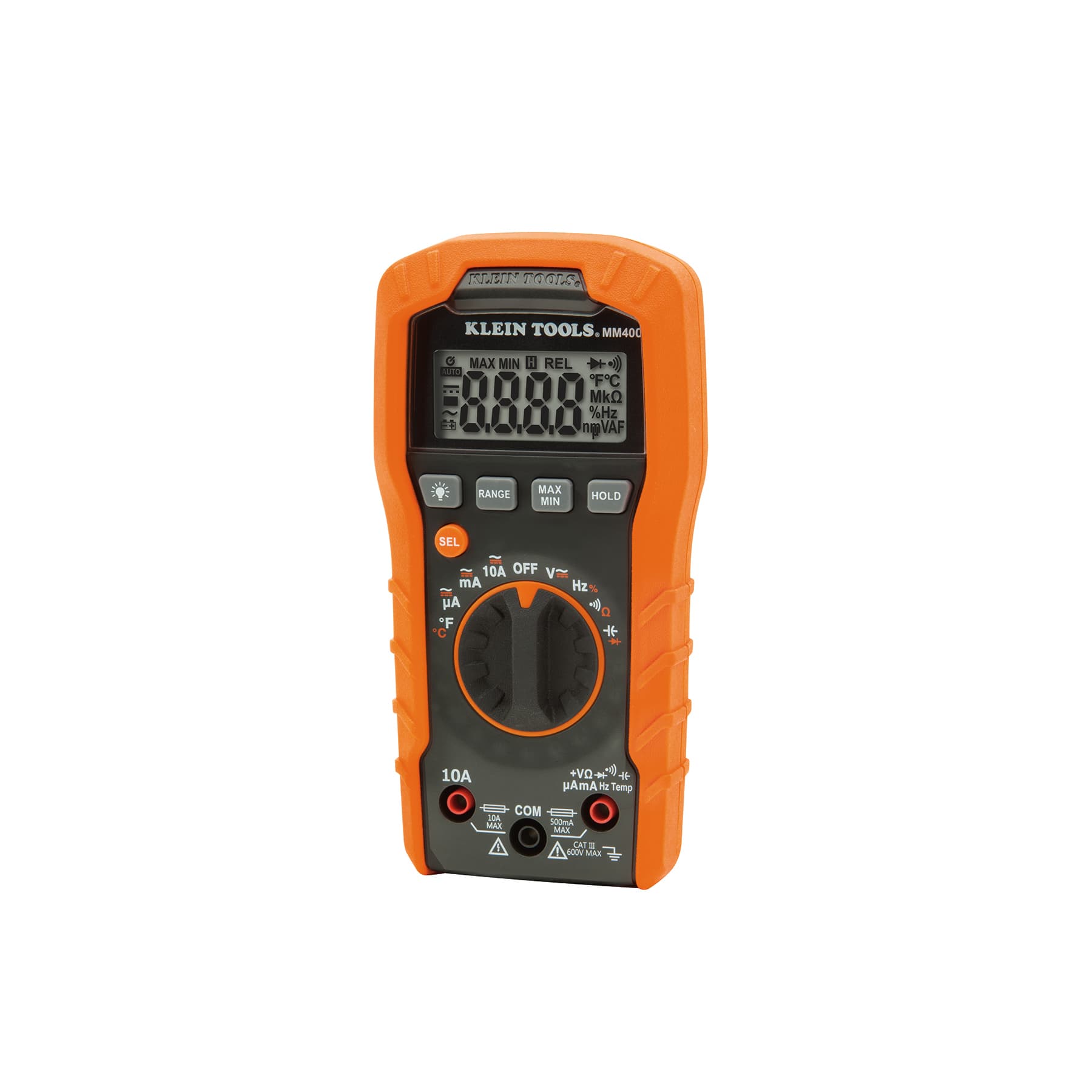
Auto-ranging, CAT III 600V, 4,000-count backlit display; also reads temperature, capacitance, frequency and duty cycle.
As an Amazon Associate I earn from qualifying purchases. Prices and availability are shown on Amazon.
Frequently asked questions
How do I know if my proximity sensor is PNP or NPN?
Check the label or part number first; many makers use a letter in the code. If it is unreadable, power it and fit a resistor from black to blue. If the black wire rises to near supply when a target is present, it is PNP. If nothing happens, move the resistor from black to brown: a black wire that drops near 0 V then means NPN.
Why does my proximity sensor LED come on but the machine does not respond?
The LED shows that the sensor has detected the target, not that the signal reached the controller. Measure at the PLC or relay input terminal. A correct voltage at the sensor but not at the input points to a broken cable or loose terminal. A correct voltage at the input points to the controller, its settings, or a PNP sensor wired to an NPN-type input.
Can I test a proximity sensor with a 9 V battery?
Sometimes, but it is below the usual 10 V minimum, so many sensors will not switch reliably or at all. Two 9 V batteries in series give 18 V, inside the typical 10–30 V DC range. A bench supply or the machine's own 24 V DC control supply is the better choice, with a resistor on the output.
What should a proximity sensor read with no target present?
For a normally open PNP sensor with a load resistor, close to 0 V between black and blue. For a normally open NPN sensor with a pull-up, close to the supply voltage. Normally closed versions read the opposite. With no resistor at all, the reading may float somewhere in between, which is not a fault on its own.
Does a stainless steel or aluminum target change the sensing distance?
Yes, for inductive sensors. Rated sensing distance is quoted for mild steel. Stainless steel, brass, aluminum and copper usually trigger at a noticeably shorter distance, often well under the rated figure; the datasheet gives correction factors. If a sensor fails only on a non-steel part, test it again with a steel target before replacing it.


