HOW-TO GUIDE
How to Test a Crankshaft Position Sensor with a Multimeter
By the OhmSavvy Research Team ·
Cranking tests and specifications
Causes at a glance
| Symptom | Likely cause | How to check | Fix or who to call |
|---|---|---|---|
| Cranks, no start, no RPM on tach or scan tool | Dead sensor, open wire or missing supply | Resistance (inductive) or reference and ground (Hall) | Repair wiring or replace sensor |
| Stalls when hot, restarts after cooling | Heat-sensitive sensor failure | Repeat the tests at operating temperature | Replace sensor; confirm with a scope if unsure |
| Coil reads OL or near 0 Ω | Open or shorted inductive winding | Ohms across the two sensor pins, unplugged | Replace sensor |
| Good resistance, no AC output | Air gap, damaged reluctor or debris on the tip | Remove sensor, inspect tip and teeth | Clean, re-seat, or a mechanic for reluctor damage |
| Hall reference or ground missing | Wiring or ECU supply fault | DC volts at the connector, key on | Trace the wire; a shop for ECU faults |
| Signal fine at sensor, missing at ECU | Open or chafed harness, corroded pin | Repeat the signal test at the ECU connector | Repair the harness or connector |
| Misfires or tach drops at speed only | Intermittent pulses or noise | Min/Max or frequency while driving; a scope | Oscilloscope diagnosis or a specialist |
Symptoms that point to the crankshaft sensor
A failing crank sensor commonly causes a crank-but-no-start, an engine that stalls and then restarts after cooling down, intermittent misfires, or a tachometer that drops to zero while the engine is still turning. A stored code in the P0335 to P0339 family commonly relates to the crankshaft position sensor circuit, but the exact meaning varies by manufacturer, and the code points to the circuit as a whole. A broken wire, a corroded connector or a damaged reluctor ring can set the same code as a dead sensor.
That is why testing matters before buying a sensor: the meter lets you split the fault between the sensor itself and the wiring that connects it to the engine computer. A quick first clue on a no-start is engine speed while cranking. If a scan tool shows zero RPM while the starter is clearly turning the engine, the computer is not receiving crank pulses, and the sensor circuit moves to the top of the list.
Inductive or Hall-effect?
Count the wires at the connector and check the wiring diagram. The two common designs behave very differently on a meter:
Inductive (magnetic), usually 2 wires
A coil around a magnet. Generates its own AC voltage as teeth pass; no power supply needed. Some add a third shield wire.
Hall-effect, usually 3 wires
Powered by a reference voltage from the computer, with a ground and a signal wire that switches on and off as teeth pass.
For the general theory of each type outside the crank application, see testing a magnetic pickup sensor and testing a Hall effect sensor. The steps below focus on diagnosing the crank circuit on a car.
1Inductive sensor: check coil resistance
With the ignition off, unplug the sensor and set the meter to ohms. Measure across the two sensor terminals and compare with the service manual range. Many inductive crank sensors fall somewhere between a few hundred and about 1,500 Ω, but the manual figure is the one that counts. An open reading (OL) means a broken coil; a reading near zero suggests shorted windings. Then measure from each terminal to the sensor body or engine ground: there should be no continuity. Wiggle the sensor lead while watching the display, because a cracked internal joint can show up only when the cable moves.
Resistance changes with temperature. Copper rises by roughly 0.4% per °C, so a coil that reads 650 Ω at 20 °C reads about 650 × (1 + 0.004 × 60) ≈ 806 Ω at 80 °C. A warm reading a little above the cold spec is normal; a reading that jumps to OL only when hot is the failure you are hunting.
2Inductive sensor: AC voltage while cranking
Set the meter to AC volts and connect across the two sensor terminals (unplugged, or back-probed at the connector if your manual allows). Have a helper crank the engine. A working sensor produces a small AC voltage that rises with speed: often a few hundred millivolts at cranking speed and several volts at higher RPM, though the manual may quote its own minimum. No reading at all, with a good resistance result, suggests an excessive air gap, a damaged reluctor or debris on the sensor tip. A magnetic sensor tip attracts steel filings, so pull the sensor and wipe it before condemning it.
3Hall-effect sensor: reference, ground and signal
A Hall sensor can't be judged with an ohmmeter, so test it powered. Identify the three wires from the wiring diagram, plug the sensor in, and back-probe at the connector with the key on:
| Wire | Meter setting | Condition | What a healthy circuit shows |
|---|---|---|---|
| Reference (supply) | DC volts to ground | Key on | The supply voltage given in the manual (often 5 V or battery voltage) |
| Ground | DC volts to battery negative | Key on | Close to 0 V, typically under about 0.1 V; higher means a poor ground |
| Signal | DC volts to ground | Turn engine slowly by hand | Switches between a low and a high level as each tooth passes |
| Signal | DC volts or frequency | Cranking | A steady in-between average on DC volts, or a frequency that rises with speed |
If the reference or ground is missing, the fault is in the wiring or the computer, not the sensor. If both are correct but the signal never switches, the sensor is the likely culprit. Turning the crankshaft by hand with a breaker bar on the pulley bolt, ignition on and the engine unable to start, is the clearest way to see individual transitions on a meter. While cranking, a DC meter averages the square wave: a 5 V signal that is high half the time reads about 5 × 0.5 = 2.5 V. A signal stuck at about 0 V or at the full reference voltage during cranking means it is not switching.
4Prove the harness all the way to the ECU
A good result at the sensor connector only proves the sensor end. Repeat the signal test at the engine computer connector, back-probing the crank signal pin from the wiring diagram. If the signal is present at the sensor but missing at the ECU, the harness between them is open or shorted. With the battery disconnected and both ends unplugged, a continuity check on each wire should read close to 0 Ω end to end and OL to ground and to its neighbors. Inductive sensors often use a shielded cable; a shield that is broken or grounded at the wrong end lets ignition noise onto the signal. Our guide to measuring continuity on a long wire covers the method.
Signal frequency: why the meter struggles
Many engines use a 60-2 trigger wheel: 60 tooth positions with two missing to mark a reference point, so 58 real teeth. The pulse rate is revolutions per second times teeth per revolution. At a cranking speed of about 200 RPM, that is (200 ÷ 60) × 58 ≈ 193 pulses per second. At an 800 RPM idle it is (800 ÷ 60) × 58 ≈ 773, and at 3,000 RPM it is 50 × 58 = 2,900. Other engines use different wheels, such as 36-1, so the exact figures change, but the scale does not.
A meter with a frequency function can confirm the pulse rate is roughly what the arithmetic predicts and rises smoothly with engine speed, which is a stronger check than AC volts alone. A frequency reading far below the prediction, or one that jumps around at a steady speed, suggests missing pulses or noise. That is the point to move from a meter to a scope.
What a multimeter can't show you
Meters for this job
Ohms and volts are enough for the basic tests. A frequency function and fast Min/Max capture make crank-signal diagnosis much easier. These picks come from our verified automotive multimeter list.
Meters with frequency and capture for sensor work
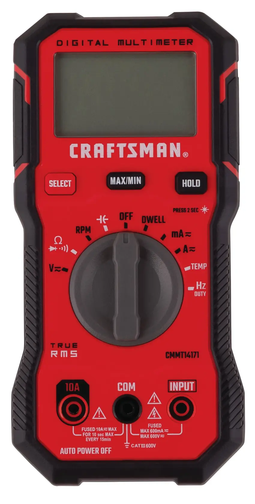
True RMS, CAT III 600V, with RPM, dwell, duty cycle, frequency and temperature.

250 µs Peak Min/Max catches brief dropouts; duty cycle to 99.9%. Average-responding, not True RMS; RPM pickup sold separately.

RPM 0 to 10,000 with the included inductive clamp, plus frequency, duty cycle, Min/Max and Hold. Marked CAT II 600V.
As an Amazon Associate I earn from qualifying purchases. Prices and availability are shown on Amazon.
Frequently asked questions
Can a bad crankshaft position sensor still pass a multimeter test?
Yes. A sensor can measure the right resistance and still drop out when it gets hot, or produce a signal with missing or distorted pulses that a meter averages away. If the engine dies when warm and restarts after cooling, test again with the engine at operating temperature, and consider viewing the signal on an oscilloscope.
Does the tachometer moving while cranking prove the crank sensor works?
On many vehicles the tachometer reading is derived from the crank signal, so a tach needle that rises while cranking suggests the computer is seeing pulses. It is a useful quick clue, not proof, because some instrument clusters use other inputs. Your service manual or a scan tool reading engine speed while cranking is more reliable.
What air gap should the crank sensor have?
It depends entirely on the engine. Many sensors are fixed in a machined bore with no adjustment, while some older designs use a shim or set gap. Use the figure in the service manual, and check that the reluctor teeth are clean, undamaged and free of metal debris stuck to the sensor tip, since debris weakens the signal.
Should I replace the camshaft sensor at the same time?
Not by default. The camshaft and crankshaft sensors do different jobs and fail independently. Read the stored codes, test the sensor the codes point to, and check the wiring to it before replacing anything. Some engines will start on the crank signal alone if the cam signal is missing, but few will run without the crank signal.
What resistance should a crankshaft position sensor have?
Only two-wire inductive sensors have a meaningful resistance, and the service manual figure is the one to trust. Many fall somewhere between a few hundred and about 1,500 ohms, but some sit outside that. OL means an open coil and a reading near zero means shorted turns. Three-wire Hall sensors contain electronics, so an ohmmeter reading across their pins tells you very little.
Will a bad crankshaft sensor throw a check engine light?
Usually, but not always. Codes in the P0335 to P0339 range commonly relate to the crank sensor circuit and often set when the computer sees cam pulses but no crank pulses. An intermittent dropout can stall the engine before a code matures, though, so a no-start with no code does not clear the sensor. Test it directly with the steps on this page.



