HOW-TO GUIDE
How to Test a Magnetic Pickup Sensor With a Multimeter
By the OhmSavvy Research Team ·

How a VR sensor makes a signal
You will find passive magnetic pickups as crankshaft and camshaft position sensors on many engines, as wheel speed sensors on older ABS systems, on transmission input and output shafts, and as speed pickups on industrial machinery. Each tooth that approaches the tip concentrates the magnetic flux through the coil, and each gap lets it relax. The coil turns that change into a voltage swing, positive as a tooth approaches and negative as it leaves.
Two-wire VR vs three-wire Hall-effect sensors
1Measure coil resistance
Ignition off, unplug the sensor connector, and measure across the two sensor pins with the meter on resistance. Compare the result with the specification for that exact part. Readings are temperature sensitive, since copper resistance rises as it warms, so a hot engine reads a little higher than a cold one; manuals often quote a value at room temperature.
Bars use a logarithmic scale: each step is ten times the last.
These ranges are typical spreads seen across common parts, not a pass mark for any specific sensor. OL means the coil or its lead is broken. A reading far below the specified value suggests shorted turns inside the coil.
2Check insulation to ground
Keep one probe on a sensor pin and touch the other to the sensor body or a clean engine ground. Repeat for the second pin. Both should read OL. Any finite resistance means the coil insulation has broken down or water has got into the sensor, and the signal will be loaded down or noisy. If the sensor passes on its own but faults return when plugged in, do the same continuity and ground checks on the harness, back to the ECU or ABS module connector.
3Read AC output while the wheel turns
Set the meter to AC volts on its lowest range, or AC millivolts if it has one, and connect across the two sensor pins. For a crank or cam sensor, back-probe the connector with it plugged in, or connect to the unplugged sensor, disable fuel or ignition per the service manual so the engine can't start, and have a helper crank it. For an ABS sensor, lift the wheel and spin it by hand. You are looking for a steady AC reading while the wheel moves and zero when it stops.
A multimeter shows only an averaged AC figure and its AC range has limited frequency response, so it can tell you a signal is present but not whether every tooth is there. To see a damaged tooth, a missing-tooth reference or a waveform that drops out intermittently, an oscilloscope is the right tool.
4Inspect the air gap and the sensor tip
A sensor that measures perfectly but makes a weak signal is often fine electrically. Pull it and look at the tip: the magnet attracts steel particles and brake dust, which bridge the gap and smear the signal. Wipe it clean. Check the tip for rubbing marks, which mean the gap has closed, and inspect the tone ring or reluctor for cracked, rusty or missing teeth.
Reading the results
| What you find | Likely cause |
|---|---|
| Resistance in spec, OL to ground, AC output when turning | Sensor healthy; check harness, connector and ECU input |
| OL across the two pins | Broken coil winding or lead; replace the sensor |
| Resistance well below spec | Shorted turns in the coil |
| Any reading from a pin to the body | Insulation breakdown or water ingress |
| Good resistance, little or no AC output | Debris on the tip, excessive gap, weak magnet or damaged wheel |
| Output fine on the sensor, missing at the ECU | Open, shorted or chafed wiring between them |
| Three wires, no meaningful resistance | Hall-effect sensor; needs a powered test instead |
Stay clear of moving parts while cranking
Meters for crank, cam and ABS sensor checks
These tests need only an ohms range and an AC volts range, but a pickup's output wanders as cranking speed rises and falls, so a meter that updates quickly or shows a bar graph makes the reading easier to follow. For a VR sensor on a car, a meter that resolves tens of millivolts matters more than a high CAT rating. Wider choices are in our automotive multimeter guide.
Meters that suit sensor diagnosis
Hands-on tested. 6,000-count backlit display, True RMS and capacitance and frequency ranges, CAT III 600V.

Hands-on tested. Its 32-segment analog bar graph tracks a pickup's AC output as engine speed changes.
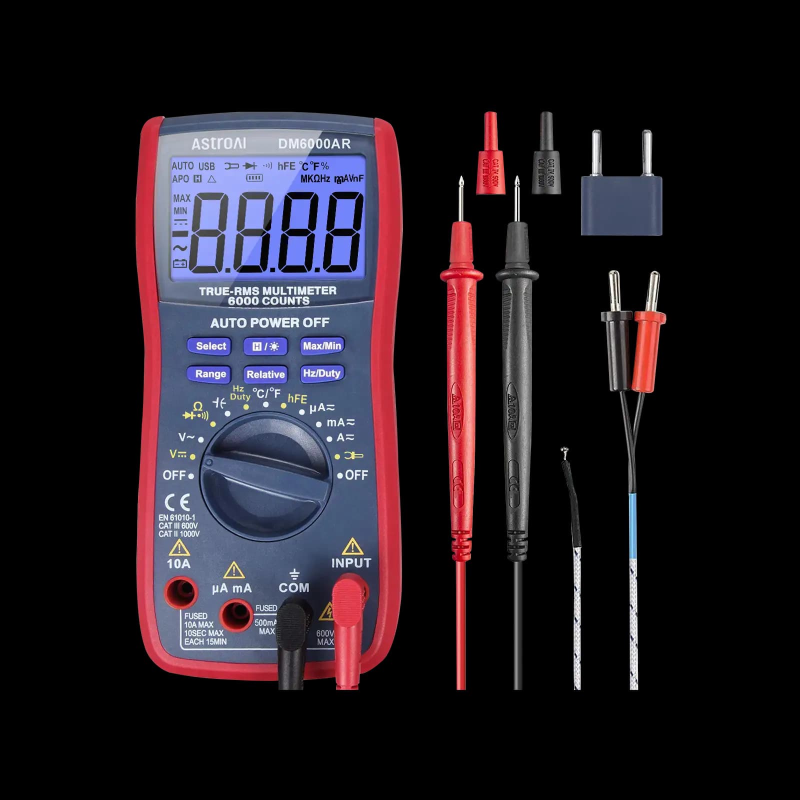
Low-cost True RMS, 6,000-count meter with manual ranging; no CAT rating stated, so keep it to vehicle wiring.
As an Amazon Associate I earn from qualifying purchases. Prices and availability are shown on Amazon.
Frequently asked questions
What resistance should a crankshaft position sensor have?
For two-wire magnetic crank sensors, coil resistance commonly falls somewhere between a few hundred ohms and around 1,500 ohms, but the figure varies a lot between manufacturers and models. Use the value in the vehicle's service information. Three-wire Hall-effect crank sensors don't have a meaningful coil resistance to measure at all.
Why does my VR sensor read correct resistance but the engine won't start?
Resistance proves only that the coil is intact. The sensor can still produce too little signal if the tip is covered in metal debris, the air gap is too large, the magnet has weakened, or the toothed wheel is damaged. The wiring and connector between sensor and ECU are also common failure points, so repeat the tests at the ECU end of the harness.
Does the AC voltage from a magnetic pickup depend on speed?
Yes. The induced voltage rises with how fast the teeth pass the tip, so output at cranking speed is much lower than at road speed. That's also why a VR sensor's signal can be too weak to read at very low speed, and why some controllers struggle to see it when the battery is weak and cranking is slow.
Does polarity matter when reconnecting a two-wire VR sensor?
It can. Reversing the two wires inverts the waveform, and some engine and ABS controllers trigger on a particular edge, which shifts the detected timing or causes errors. Keep the original connector orientation and, if the wiring has been repaired, check it against the wiring diagram.
Can I test a guitar pickup the same way?
The principle is the same: a magnet and a coil, with the strings changing the field instead of a toothed wheel. A DC resistance check across the output shows whether the coil is intact, and typical single-coil and humbucker pickups measure in the kilohm range. An open reading usually means a broken coil wire or a bad solder joint.

