HOW-TO GUIDE
How to Test a Current Limiting Resistor With a Multimeter
By the OhmSavvy Research Team ·

1Work out the value it should be
A measurement is only useful if you know what to compare it with. For a resistor feeding an LED, the designer subtracts the LED's forward voltage from the supply and divides what is left by the current they wanted: R = (Vsupply − Vf) / I. Forward voltage depends on the color and the exact part, so take it from the LED datasheet; red indicators are typically around 2V and white or blue ones around 3V. The result is then rounded up to the next standard value.
| Supply | LED (typical Vf) | Target current | Calculated R | Common fitted value |
|---|---|---|---|---|
| 5 V | Red, ~2.0 V | 20 mA | 150 Ω | 150 Ω |
| 5 V | White, ~3.1 V | 15 mA | 127 Ω | 130 Ω or 150 Ω |
| 12 V | White, ~3.1 V | 20 mA | 445 Ω | 470 Ω |
| 3.3 V | Red, ~2.0 V | 10 mA | 130 Ω | 130 Ω to 150 Ω |
| 24 V | Green, ~2.2 V | 10 mA | 2.18 kΩ | 2.2 kΩ |
2Read the color bands or SMD code
If you can't trace the design, the part tells you its intended value. On a four-band through-hole resistor the first two bands are digits, the third is the multiplier and the fourth is tolerance, so brown-green-brown-gold is 150 Ω ±5% and yellow-violet-brown is 470 Ω. Five-band precision parts add a third digit. Heat can darken the bands until red and brown, or orange and brown, look alike, which is one more reason to measure rather than trust the paint on a part that has run hot.
Surface-mount resistors use printed codes. A three-digit code is two digits and a multiplier, so 151 means 150 Ω and 471 means 470 Ω; four-digit codes such as 1500 add a third significant digit. An R marks the decimal point, as in 4R7 for 4.7 Ω. Codes made of two digits and a letter belong to the EIA-96 system and need its lookup table. Many 0402 and smaller parts carry no marking at all.
3Compare the in-circuit and lifted-leg readings
Switch the circuit off and discharge any large capacitors. Measure across the resistor where it sits first; it costs nothing. The meter's test voltage is usually too low to switch on the LED, but the pads may still share a path through a driver IC, a transistor or a parallel branch, and any such path can only make the reading lower. So an in-circuit reading that is higher than the marked value plus tolerance is a real fault, while one that is lower is not proof of anything yet.
For a definite answer, desolder one leg of a through-hole part, or one end of an SMD resistor, and measure again. Touch the probes together first and subtract the lead resistance if you are checking a low value. A healthy part reads within its tolerance band of the marked value. Our parallel resistance guide explains why the parallel paths pull the number down.
4Check the voltage drop under power
A resistor can measure perfectly cold and still leave you wondering whether the LED is getting the right current. Power the circuit, set the meter to DC volts and probe both ends of the resistor. Divide that voltage by the resistance you measured and you have the current through it, with no need to break the circuit and insert the meter in series. Then probe across the LED: the two readings should add up to the supply, give or take wiring losses.
If the resistor shows close to the full supply and the LED shows almost nothing, either the LED is shorted (the resistor gets hot) or the resistor is open (it stays cold and the LED is dark). A reading near zero across the resistor with the LED dark means no current is flowing at all, so look for an open LED, a broken track or a driver that is switched off.
5Check the power rating and look for burn signs
Every resistor turns its current into heat at P = V × I. In the 12V example that is roughly 8.6V × 18 mA, or about 0.16 W: comfortable for a 1/4 W part, marginal for a 1/8 W one, and too much for a tiny 0402 SMD resistor. On 24V supplies the dissipation rises further. An undersized resistor runs hot, its value creeps, and it eventually goes open.
- Bands darkened, blistered or hard to read compared with nearby resistors.
- A brown ring or scorch mark on the PCB under or around the body.
- A cracked body or a chip resistor with a visible split across its top.
- A lifted-leg reading well above tolerance, or one that drifts as the part warms in your fingers.
Replace the cause, not just the part
Reading the results
| What you measure | Likely cause |
|---|---|
| Lifted-leg value within tolerance, LED current near target | Resistor healthy; look elsewhere |
| Lifted-leg reading well above marked value | Resistor drifted from heat or ageing; replace |
| OL with one leg lifted | Resistor open, often after overheating |
| In-circuit reading lower than marked, lifted reading correct | Parallel path through other parts, not a fault |
| Near full supply across resistor, LED dark, resistor hot | Shorted LED pulling excess current |
| Near full supply across resistor, LED dark, resistor cold | Resistor open in circuit |
| Near 0V across resistor, LED dark | No current: open LED, broken track or driver off |
Keep the probes off the supply rails
Meters for resistor and LED circuit checks
Checking a current-limiting resistor uses three ranges: ohms with a leg lifted, DC volts across it under power, and sometimes DC milliamps in series with the LED. A 6,000-count meter reads a 330 Ω part to a tenth of an ohm on its 600 Ω range, more than enough to judge a 5% tolerance band. For the powered check in more depth, see how to measure voltage across a resistor.
Meters for resistor and LED checks
Value auto-ranging meter covering ohms, DC volts and current for LED and indicator circuits.
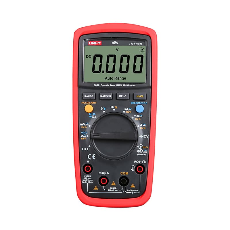
6,000-count resolution with manual ranging, useful for reading small resistor values precisely.

Hands-on tested. CAT III 600V Fluke for indicator circuits inside mains equipment and panels.
As an Amazon Associate I earn from qualifying purchases. Prices and availability are shown on Amazon.
Frequently asked questions
What happens if an LED's current limiting resistor goes open?
The LED goes dark because no current can reach it. Under power, the voltage across the open resistor reads close to the full supply, and the LED itself shows little or nothing. With power off, the resistor reads OL once one leg is lifted. Carbon film resistors that have been overheated often fail this way.
Can I use a higher value resistor than the one I calculated?
Yes. A higher value simply lets less current through, so the LED is a little dimmer and runs cooler. Going one standard value up from the calculated figure is normal practice. Going lower is the risky direction, because it raises the current above what the LED is rated for.
Why does my resistor read lower in the circuit than its marked value?
Your meter is measuring the resistor in parallel with everything else connected across its two pads, such as a driver chip, a transistor or another branch. Parallel paths can only lower the reading. Lift one leg, or desolder one end of an SMD part, and measure again before deciding the resistor is faulty.
Do I need a 1/4 W resistor for an LED?
Work it out with P = I² × R, or P = V × I using the voltage across the resistor. A 20 mA indicator LED on 5V dissipates only a few tens of milliwatts in its resistor, so even a small part is fine. On 12V or 24V supplies the resistor drops much more voltage and the dissipation climbs, so check it and leave at least a factor of two of headroom.
Is the resistor value on an LED strip the same as a single LED?
No. Strips put several LEDs in series with one resistor per segment, so the sum of the LED forward voltages is subtracted from the supply before dividing by the current. The test method on this page still applies to each segment resistor, but the expected value comes from the strip's own design.


