HOW-TO GUIDE
How to Measure Continuity on a Long Electrical Wire
By the OhmSavvy Research Team ·
Confirm the wire is dead before any resistance test
- Switch off and lock out the breaker, then confirm zero volts at both ends with a voltage test on a meter rated for the circuit's CAT category.
- Disconnect the wire from loads and devices at both ends. Anyone working at the far end must know the circuit is under test.
- Never push a metal fish tape into a box or conduit that holds live conductors.
Why long wires are awkward to test
A continuity test needs a closed path from one probe, through the wire, to the other probe. On a short lead or a car harness both ends are within arm's reach; our guide to testing electrical wires with a multimeter covers that case. On a cable run between rooms, floors or buildings, the far end may be tens of meters away. You need a way to bring the far end back to the meter, and you need to know what a long but healthy wire should read, because its resistance is no longer close to zero.
1De-energise and isolate the circuit
Long runs bring a hazard that short wires rarely do: induced voltage. A dead conductor that runs alongside live cables can pick up a capacitively coupled "ghost" voltage, and a disconnected run may still be connected to something you didn't expect at the far end.
Use the voltage range first. If you see a reading, find its source before going any further. A low-impedance mode, where your meter has one, loads the wire so ghost voltage collapses while a genuine supply does not. Only switch to continuity or resistance once the wire reads zero, because any voltage on the conductor will upset the reading and can damage the meter.
2Use the loop method: jumper the far end
Pick a return conductor you trust: another core in the same cable, the ground conductor, or a spare wire pulled alongside. At the far end, join it to the wire under test with a wire nut, a clip lead or a terminal block. At the near end, measure resistance between the two.
- Short your probe tips together and note the lead resistance, or use the meter's relative mode to zero it.
- Measure across the two conductors at the near end with the far-end jumper in place.
- Remove the jumper and measure again. You should now see OL. A low reading without the jumper means the two conductors are shorted to each other or connected through something else.
Why the second reading matters
3Use a long test lead instead
When no return conductor is available, run a temporary lead back from the far end: a reel of hookup wire or a spare extension cord conductor works. Connect it to the far end of the wire under test, bring it back to the meter, and measure. Measure the temporary lead on its own as well, by joining its ends, and subtract its resistance from the total.
Expected resistance of long copper wire by AWG
Copper resistance depends on gauge, length and temperature. The figures below are typical values for solid annealed copper at 20 °C; stranded wire reads slightly higher, and resistance rises by roughly 0.4% per °C as the wire warms. Use them to judge whether a measured value is plausible.
| AWG | Ω per 100 ft (single conductor) | Ω per 100 m | 100 ft run, loop of 2 |
|---|---|---|---|
| 22 | ≈ 1.61 | ≈ 5.30 | ≈ 3.23 Ω |
| 20 | ≈ 1.02 | ≈ 3.33 | ≈ 2.03 Ω |
| 18 | ≈ 0.64 | ≈ 2.09 | ≈ 1.28 Ω |
| 16 | ≈ 0.40 | ≈ 1.32 | ≈ 0.80 Ω |
| 14 | ≈ 0.25 | ≈ 0.83 | ≈ 0.50 Ω |
| 12 | ≈ 0.16 | ≈ 0.52 | ≈ 0.32 Ω |
| 10 | ≈ 0.10 | ≈ 0.33 | ≈ 0.20 Ω |
Scale linearly with length: a 250 ft run of 14 AWG tested as a loop is about 500 ft of copper, roughly 1.26 Ω. On very thin cable over long distances, the total can exceed the meter's beep threshold even though nothing is broken, so read the number rather than waiting for a tone.
Testing with a fish tape while pulling cable
A steel fish tape is already a long conductor that reaches the far end. Once it is pushed through an empty conduit, hook the far end of the wire to its head and measure between the tape at the near end and the wire. Steel has far higher resistance than copper, so treat this as a pass-or-fail continuity check rather than a resistance figure.
When pulling new cable, loop-test each conductor again after the pull, so damage from a sharp bend or a burr at a fitting shows up before the walls are closed.
Reading the results
| Reading | What it usually means |
|---|---|
| Close to the expected value; OL with jumper removed | Wire is continuous and not shorted |
| OL with the jumper in place | Open somewhere in the wire, return or jumper. Swap the return to isolate it |
| Several times higher than expected | Corroded splice, loose terminal or broken strands |
| Low reading with the jumper removed | Conductors shorted together, or a load still connected |
| Reading drifts or won't settle | Residual voltage, cable capacitance charging, or a poor probe contact |
For a beep that cuts in and out as you flex the cable, see why a continuity beep cuts out. If the display shows OL and you aren't sure why, our explainer on what OL means on a multimeter covers every case.
Which multimeter suits long cable runs
Any meter with a resistance range can do the loop test. For building wiring, choose one rated for the CAT category of the circuit, since the same meter does the dead test first.
Meters in our reviews
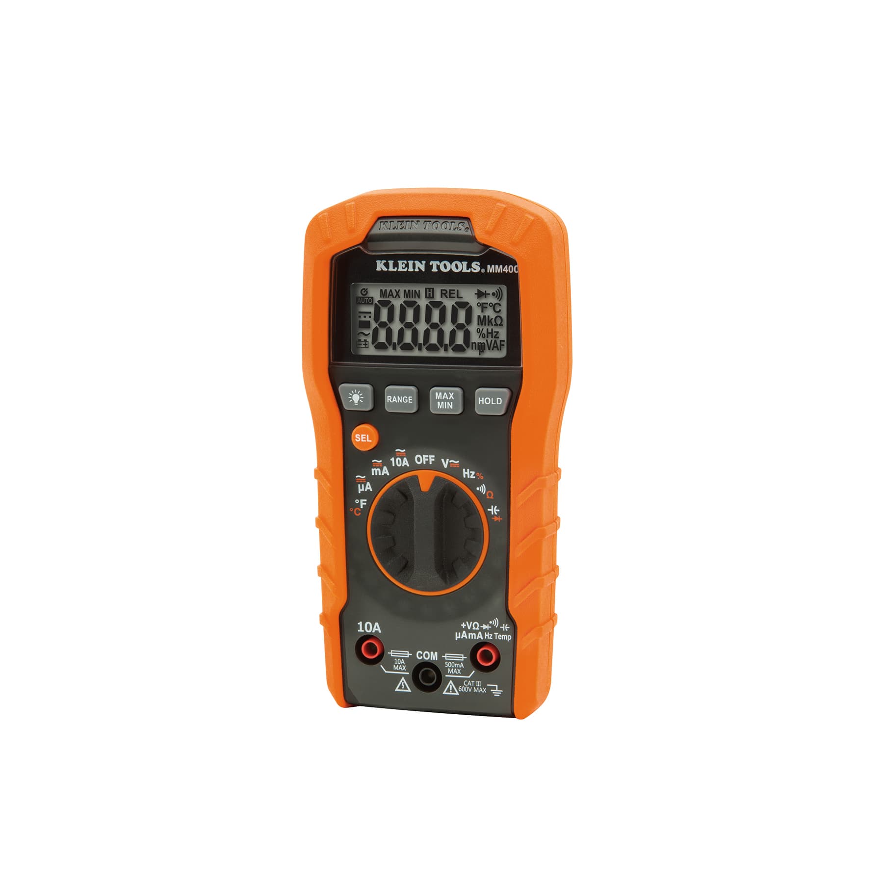
Auto-ranging, CAT III 600V, with temperature and capacitance. Not True RMS; discontinued by Klein.

CAT IV 600V / CAT III 1000V for runs back to the service entrance, with a 6,000-count display for low-ohm readings.

True RMS, CAT III 600V, with non-contact voltage detection built in for a quick first check.
As an Amazon Associate I earn from qualifying purchases. Prices and availability are shown on Amazon.
Frequently asked questions
How do you check wire continuity with a multimeter?
Disconnect the wire from power, set the multimeter to continuity mode (the diode/sound-wave symbol), and touch one probe to each end of the wire. A good wire beeps and reads near 0 Ω; no beep and an OL reading means it's broken somewhere along its length. On a run too long to reach both ends at once, see the fish-tape and reflected-loop methods below.
How much resistance is too much for a long wire?
Compare the reading with the expected copper resistance for that gauge and length. For a loop, double the run length. A result close to the calculation, plus a few tenths of an ohm for leads and connections, is a pass. A reading several times higher than expected suggests a corroded splice, a loose terminal or broken strands, even if the meter still beeps.
Why does my meter beep on one long wire but not another?
The continuity beeper only sounds below a threshold set by the meter, often in the tens of ohms, depending on the model. A long run of thin wire can exceed it while still being perfectly intact. Switch to resistance mode and compare the actual value with the expected figure for its gauge and length instead of relying on the beep.
Can I use the ground wire to test continuity on a long run?
Yes, if the ground conductor itself is known to be good and the circuit is isolated. Jumper the suspect wire to ground at the far end and measure between them at the near end. Remove the jumper afterwards. Using conduit or a metal box as the return also works, but those paths are less predictable, so treat the result as pass or fail.
What is ghost voltage on a disconnected wire?
It is voltage coupled capacitively from nearby live conductors into a wire that is not connected to anything. A high-impedance digital meter can display tens of volts that collapse as soon as any load is applied. A low-impedance (LoZ) mode loads the wire enough to make ghost voltage disappear, while a real supply stays put.
How do I identify which wire is which in a long cable?
Twist two conductors together at the far end, then measure pairs at the near end until one reads low: those are the two you joined. Mark them, move the jumper to a different pair and repeat. With three or more conductors this identifies every wire. Remove all jumpers before reconnecting the circuit.

