HOW-TO GUIDE
How to Test a Reed Switch Using a Multimeter
By the OhmSavvy Research Team ·
Disconnect before testing, and handle with care
- Remove power and disconnect the switch from its circuit before a continuity or resistance test. On an alarm system, put the panel into test or service mode first so you don't trigger the siren or a monitoring call.
- Reed switches are sealed in thin glass. Don't squeeze the body with pliers or bend the leads right at the glass.
NO, NC and changeover reed switches
A reed switch is a pair of flexible ferromagnetic blades sealed in a glass tube. A magnetic field magnetises the blades so they attract and touch; remove the field and their spring tension pulls them apart. Knowing which type you have tells you what each reading should be.
| Type | Leads | No magnet | Magnet present |
|---|---|---|---|
| Normally open (NO, Form A) | 2 | Open: OL | Closed: near 0 Ω |
| Normally closed (NC, Form B) | 2 | Closed: near 0 Ω | Open: OL |
| Changeover (SPDT, Form C) | 3: common, NO, NC | Common to NC closed, NO open | Common to NO closed, NC open |
Normally open reeds are by far the most common. Some NC parts are actually NO reeds held closed by a small built-in bias magnet, so a strong test magnet in the wrong orientation can behave unexpectedly.
1Set up the meter
Select continuity mode for a quick audible check, or resistance for an actual contact-resistance figure. Touch the probes together first: note the lead resistance, typically a few tenths of an ohm. Clip the probes onto the switch leads with alligator clips if you can, so both hands are free for the magnet. For a changeover reed, identify the common lead first: it is the one that shows continuity to one of the other two leads in both magnet states.
2Do the magnet test
Read the switch with no magnet nearby. Then bring a magnet slowly toward it, held parallel to the glass tube, and watch for the reading to change state. Pull the magnet away and the reading should return. Repeat several times: a good reed switches cleanly and identically every time.
Orientation and null zones
Pull-in vs drop-out distance
Pull-in (operate) is the point at which the contacts close as the magnet approaches. Drop-out (release) is the point at which they reopen as it moves away. Because the blades need less field to stay together than to close in the first place, drop-out happens at a greater distance than pull-in. That built-in hysteresis stops the switch chattering when a door rattles slightly.
To check it, lay the switch on a ruler, slide the magnet in from a distance and note where the meter changes, then slide it back out and note where it changes again. Look for consistency between attempts, not a particular number.
3Test door and window alarm sensors
Wired door and window contacts are usually a reed in a plastic housing on the frame, with the magnet on the door. Most are wired so the loop is closed when the door is shut. Disconnect the two sensor wires at the panel or at a junction, then measure across them while opening and closing the door.
- Door shut: low resistance. Door open: OL.
- If the reading at the panel shows a fixed resistance rather than near 0 Ω, the loop may include an end-of-line resistor. Look for a change between that value and OL instead.
- If the sensor works on the bench but not on the door, check the gap between the two halves against the sensor's rated gap, and check that the door hasn't sagged out of alignment.
- If the sensor is fine but the loop still reads open, the fault is in the cable; the methods in testing electrical wires with a multimeter apply.
01
Disarm / test mode
Avoid a false alarm
02
Disconnect
Isolate the two wires
03
Door shut
Expect low Ω
04
Door open
Expect OL
05
Repeat
Same result every time
Reading the results
| What the meter shows | What it usually means |
|---|---|
| Changes state cleanly with the magnet, every time | Good switch |
| NO reed reads near 0 Ω with no magnet nearby | Contacts welded or stuck closed |
| OL whatever you do with the magnet | Open lead, cracked glass, or magnet too weak or badly oriented |
| Closes, but reads several ohms or more | Contaminated or worn contacts |
| Reading flickers or the beep stutters when tapped | Intermittent contact or a hairline crack in the glass |
| Only switches with the magnet touching | Weak magnet, or a switch that has lost sensitivity |
For a stuttering beep, see why a continuity beep cuts in and out; it helps separate a faulty switch from a loose probe connection.
Glass fragility, stuck contacts and intermittent operation
The glass envelope is the weak point. If you need to bend or trim the leads, grip the lead with pliers between the glass and the bend so the stress doesn't reach the seal. A cracked seal lets air in, the contacts oxidise, and the switch becomes unreliable long before it fails outright.
Welded contacts usually trace back to the load: switching more current than the reed is rated for, or the inrush of a capacitive load or lamp. Replacing a welded reed without addressing the load usually means another failure.
For intermittent operation, hold the magnet at the switching point and tap the housing gently with a plastic tool while watching the display. A Min/Max mode, where fitted, records a dropout you might miss.
Which multimeter you need
Any digital meter with continuity and resistance modes will do. A fast continuity beeper makes the magnet test quicker, since you can watch the switch instead of the display. For a refresher on each mode, see how to use a multimeter.
Meters in our reviews
Pocket-sized and auto-ranging, with a built-in non-contact voltage detector. Extech doesn't state True RMS.

True RMS, CAT II 600V, smart auto-ranging and a backlit display for home use.
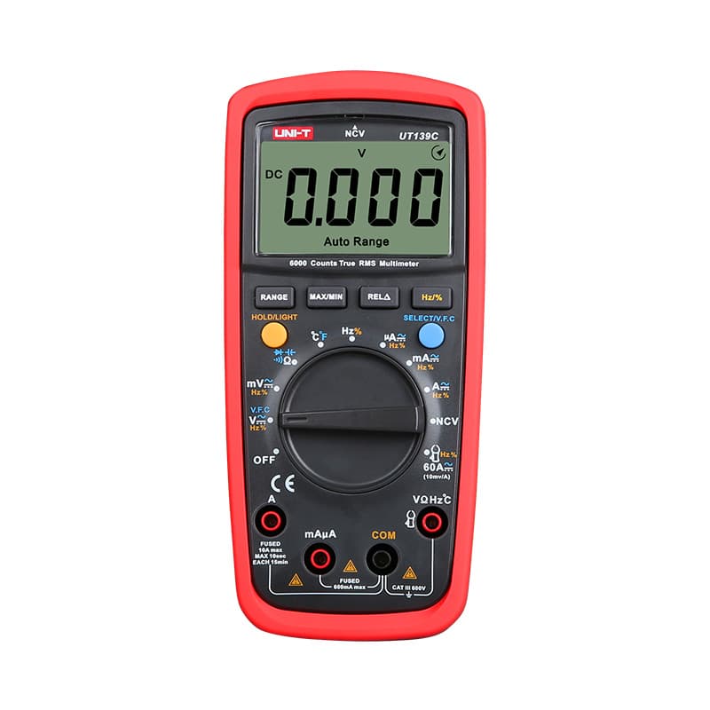
True RMS, 6,000-count, both auto and manual ranging, with non-contact voltage detection.
As an Amazon Associate I earn from qualifying purchases. Prices and availability are shown on Amazon.
Frequently asked questions
What resistance should a closed reed switch have?
Very low. Small reed switches typically have a contact resistance well under one ohm, with datasheets often quoting a maximum in the region of 100 to 200 milliohms. On a multimeter, that usually looks the same as touching the probes together. A closed reading of several ohms or more suggests worn or contaminated contacts.
How close does a magnet need to be to close a reed switch?
It depends on the magnet's strength, its orientation and the switch's sensitivity. A small reed with a typical fridge-strength magnet may only operate within a few millimeters, while a stronger magnet works from further away. Door and window alarm contacts specify a rated gap on their packaging or datasheet, which is the figure to test against.
Can a reed switch go bad?
Yes. The most common failures are contacts welded shut after switching too much current, a cracked glass envelope that lets the contacts oxidise, and reeds that lose their spring and stop opening reliably. Reed switches are rated for very large numbers of operations at low loads, but a single overload can damage them.
Why does my reed switch close twice as I slide the magnet past?
That is normal for a magnet held parallel to the switch and moved along it. The field strength across the contact gap rises, falls and rises again as different parts of the magnet pass, so the switch can close, open briefly and close again. Mark the position where it operates most cleanly when mounting the magnet.
How do I test a wireless door sensor's reed switch?
Remove the battery, open the case and find the small glass reed on the circuit board. Put the meter probes across its two solder pads in continuity mode, then move the magnet half of the sensor toward and away from it. Many wireless sensors use a reed, though some use a Hall-effect sensor instead, which this test can't check.



