HOW-TO GUIDE
How to Solder Stranded Wire Without Solder Wicking Too Far
By the OhmSavvy Research Team ·

Safety: hot tips, hot strands and fumes
- Copper conducts heat well, so the wire can be too hot to touch several centimeters from the joint. Hold it in a clamp, helping hands or pliers, never in your fingers.
- Flux smoke irritates the eyes and airways. Work with ventilation or a fume extractor, and keep your face out of the plume.
- Wires with leaded solder or old insulation: wash your hands afterwards and keep food off the bench. Park the iron in its stand between joints and switch it off when you finish.
What solder wicking is and why it causes failures
A stranded wire is a bundle of thin copper strands with tiny gaps between them. When those strands are hot and fluxed, molten solder is pulled into the gaps the same way water climbs a paper towel. That is exactly what you want inside the joint. The problem starts when the solder keeps going past the joint, along the bare strands and up under the insulation.
Everywhere the solder reaches, the wire stops being a flexible bundle and becomes a solid rod. The wire still has to bend somewhere, so all the flexing now happens at one point: the end of the solder. Repeated bending or vibration fatigues the strands at that line until they snap one by one. Because the line is often under the insulation, the failure is invisible until the connection goes intermittent.
01
Joint
Solder fully wets the strands here
02
Rigid zone
Keep it no longer than the joint needs
03
Flexible gap
Bare strands with no solder
04
Insulation
Should stay solder-free underneath
05
Strain relief
Heat-shrink spans the stiff edge
Industry workmanship standards, such as IPC J-STD-001, treat solder wicking into the part of a wire that must stay flexible as a defect. If you build to a standard, check its exact acceptance criteria. For hobby work, the practical rule is simple: solder where the joint is, bare copper between the joint and the insulation, and no solder under the insulation.
The method at a glance
01
Strip to length
Only what the joint needs
02
Flux the joint end
Not the whole bare section
03
Clip a heat sink
Between joint and insulation
04
Heat briefly
Feed a measured amount of solder
05
Inspect & shrink
Check the line, add strain relief
1Strip only what the joint needs
Work out how much bare wire the joint actually uses: the depth of a solder cup, the length of a lap or twist splice, or the hook around a terminal post. Strip that length plus a small margin, so a short gap of bare strands remains between the solder and the insulation edge. A gap of roughly one wire diameter is a common target. Stripping far more than you need gives the solder a long, inviting runway and the iron more copper to heat. Twist the strands lightly in their original lay direction so none stray, and don't nick them: a nicked strand is a weak point before you even start. If the joint will sit in a connector, follow the connector's strip-length instructions.
2Put flux only where solder belongs
Solder flows wherever there is hot, fluxed copper. Brushing liquid flux along the whole bare section, or dipping the wire in a pot of it, invites solder all the way to the insulation. Apply flux only to the part of the strands that goes into the joint. Rosin-core solder already carries flux in its core, and for many wire joints that is enough on its own. If you add extra flux, use a fine flux pen or a small dab of paste on the joint end only.
3Clip a heat sink behind the joint
Clamp a crocodile clip, hemostat or purpose-made heat sink clip onto the bare strands between the joint and the insulation. The metal jaws draw heat out of the wire at that point, so the strands behind the clip stay below the solder's melting point and the solder stops there. The clip doubles as a physical marker for where the solder line should end. This is the same tool our guide to soldering wires without overheating insulation recommends, and it does both jobs at once. Leave the clip in place until the joint has cooled.
4Short heat, measured solder
Use a clean, freshly tinned tip at a normal working temperature and a tip shape with enough contact area for the wire gauge. A chisel or bevel tip usually transfers heat into a wire much faster than a fine conical one; see soldering iron tip types. Touch the tip to the joint, feed solder into the joint on the side away from the tip, and take the iron away as soon as the solder has flowed into the strands and the surface looks smooth. On small and medium wire this typically takes a few seconds; heavier gauges take longer.
Feed only as much solder as the joint can hold. Excess solder has nowhere to go but along the strands. Thinner solder wire makes it easier to meter small amounts; our solder wire diameter guide covers sizes. If the solder won't flow quickly, don't hold the iron there longer. Lift off, clean and re-tin the tip, and check the temperature against our temperature guide.
5Inspect where the solder stops
Once the joint is cool, bend the wire gently a short way behind the joint and look at the bare section, using a magnifier if the wire is fine. You are checking three things:
Good
Strands wetted inside the joint, solder ends cleanly, a short bare gap still flexes before the insulation.
Wicked too far
Solder runs to or under the insulation; the wire is stiff right up to the jacket and bends sharply there.
Not wetted
Solder sits as a lump on the outside with dull strands showing; the joint is weak and may be high resistance.
If the wire feels stiff where it enters the insulation, the solder has traveled under it. The dependable fix is to cut back and redo the joint. To check a finished cable electrically, a continuity test end to end while you flex it near the joint will reveal an intermittent break; our guide to testing electrical wires with a multimeter shows how.
6Add strain relief and heat-shrink
Even a well-controlled joint has a stiff section, so give the wire something to spread the bend over. Heat-shrink tubing that covers the joint and extends well onto the insulation on each side moves the flex point away from the end of the solder and spreads it over a longer length. Adhesive-lined (dual-wall) tubing adds stiffness and seals out moisture. Remember to slide the tubing on before you make the joint. Inside equipment, a cable tie or clamp that stops the wire from moving at the joint helps just as much.
The 10 mm overlap is an example, not a rule. On wire that will flex a lot, longer overlap or a second, larger layer of tubing over the first gives a more gradual transition. Check the tubing's datasheet for its shrink ratio so it grips both the joint and the insulation.
Causes of solder wicking too far, and the fixes
| Cause | What happens | Fix |
|---|---|---|
| Iron held on too long | Heat soaks down the strands and solder follows it | Clean, tinned tip at working temperature; lift off as soon as it flows |
| Tip too small for the wire | Slow heat transfer forces a long dwell | Use a chisel or bevel tip sized to the wire |
| Too much solder fed | Excess solder runs along the strands | Feed only what the joint can hold; use thinner solder wire |
| Flux on the whole bare section | Solder wets everything the flux touched | Flux the joint end only; rely on the solder's core flux |
| Strip length far too long | A long fluxed runway toward the insulation | Strip to the joint length plus a small gap |
| No heat sink on fine wire | Thin wire heats along its length quickly | Clip a heat sink between the joint and the insulation |
When crimping is the better choice
Soldering is a good fit for many connections, but the stiff transition it creates is a real weakness on wire that moves or vibrates. That is why vehicle, aircraft and machinery wiring commonly relies on crimped terminals made with the correct tool. For solder cups, pins and strain relief on small connectors, see how to solder small-gauge stranded wire to a connector. Requirements vary by industry and manufacturer, so treat this as a general guide:
| Situation | Usually better | Why |
|---|---|---|
| Wire to PCB pad or solder cup, little movement | Solder | Small, low-resistance joint; the board or connector holds the wire still |
| Splice inside an enclosure, wire secured | Solder, with heat-shrink | Compact and reliable when the wire can't flex at the joint |
| Engine bay or other high-vibration area | Crimp | No rigid soldered section for vibration to fatigue |
| Wire that is flexed repeatedly | Crimp, or solder with generous strain relief | Bending concentrates at the end of the solder |
| Screw terminal | Bare strands or a crimped ferrule | Solder-tinned ends can deform under clamping pressure and loosen |
If you do solder in a vibration-prone spot, support the wire close to the joint so the joint itself never carries the movement. Our guide to the best soldering iron for automotive electronics covers in-car work, and how to solder wires together walks through a complete splice. If you are fitting coax plugs, see how to solder a coaxial cable connector.
The one-line rule
Irons that make short joints easier
Any iron that reaches a proper working temperature and accepts a suitably sized tip can make wire joints without runaway wicking; technique matters more than the tool. Adjustable, temperature-controlled irons make it easier to finish each joint quickly. These are from our best soldering irons roundup, and the how to use a soldering iron guide covers the basics.
Soldering irons in our reviews
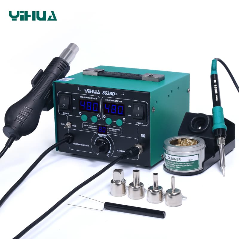
100W station, closed-loop control from 50 to 480°C, ESD safe. Hakko's replacement for the FX-888D, for serious hobbyists and repair benches.
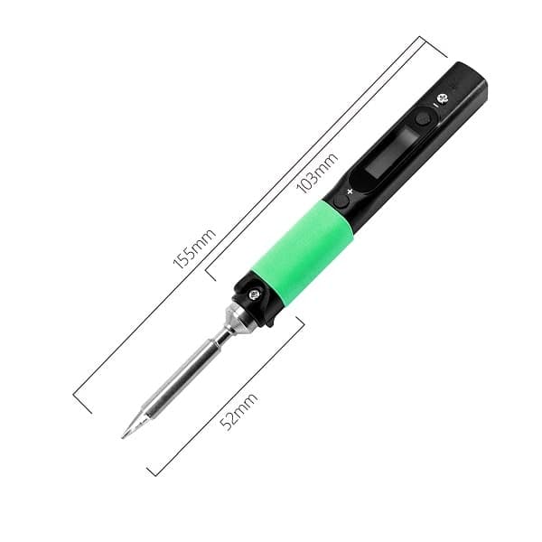
About 60W from 20V USB-C PD (up to 88W at 24V), ~12 second heat-up, OLED display. Best for portability and field repairs.
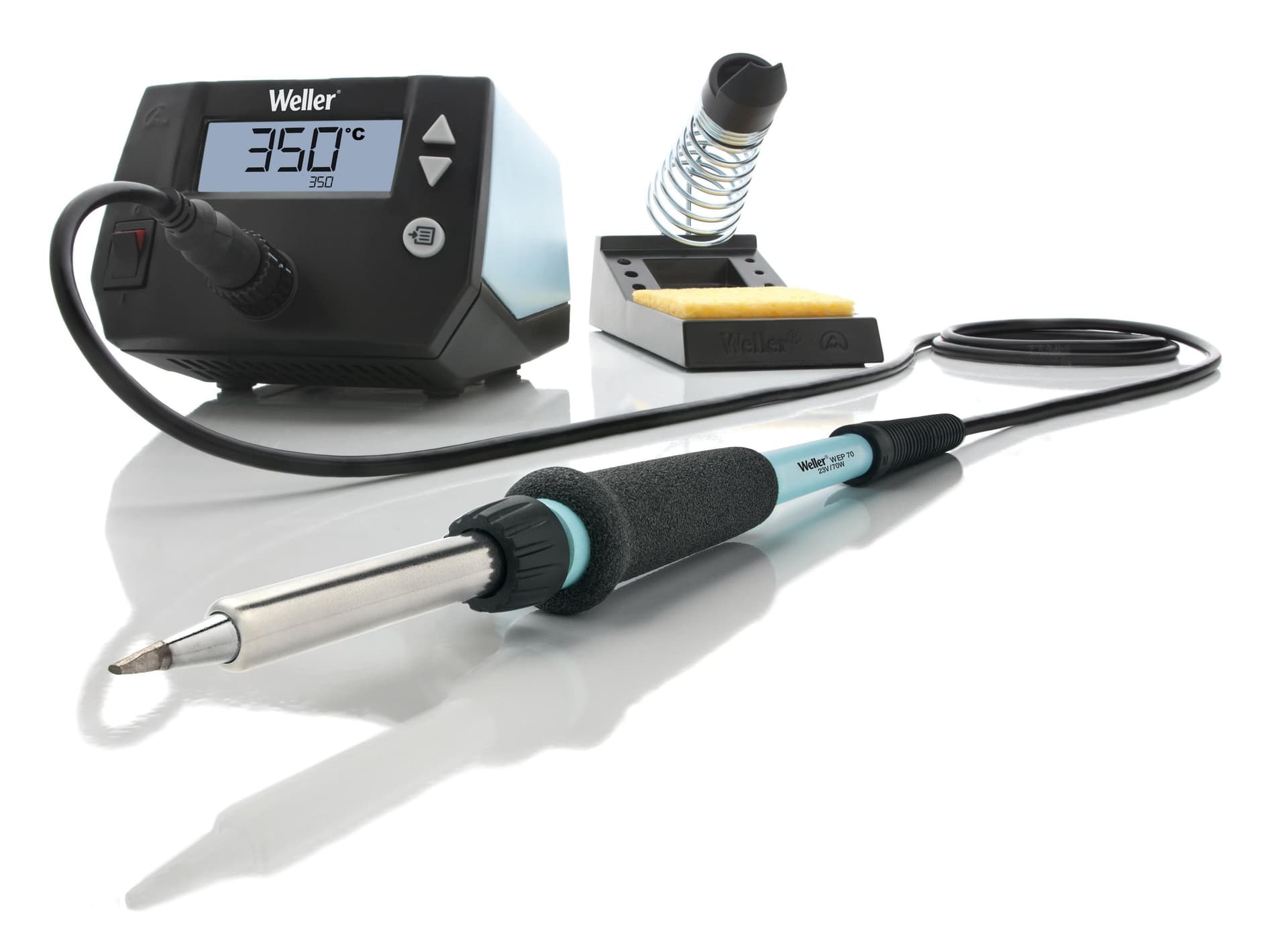
85W digital, ESD-safe station (70W iron) with about 28 second heat-up, for dedicated workbenches.
As an Amazon Associate I earn from qualifying purchases. Prices and availability are shown on Amazon.
Frequently asked questions
Why does stranded wire break right next to the solder joint?
Solder turns the strands into one rigid rod. When the wire is bent or vibrates, all the flexing concentrates at the point where that rigid section meets the loose strands, and the copper fatigues there. The break is often hidden under the insulation, so the wire can look fine while one or more strands have already snapped.
Does a hotter soldering iron make solder wick further?
Not by itself. What drives wicking is how much of the wire gets above the solder's melting point, and that depends mostly on how long heat flows into it. A properly hot, well-tinned tip often finishes the joint in a couple of seconds, while a cooler iron held on longer can soak heat much further down the strands.
Can you fix a wire that already has solder wicked under the insulation?
The reliable fix is to cut the wire back past the stiff section, strip it again and redo the joint. Trying to pull the solder back out with braid adds more heat and rarely clears the strands under the insulation. If the wire is too short to cut back, splice in a new length and protect the splice with heat-shrink.
Should you tin stranded wire before crimping it?
Generally no. A crimp works by compressing the strands into a gas-tight joint, and solder can slowly deform under that pressure, loosening the connection over time. It also leaves a stiff point right at the back of the crimp. Crimp bare, clean strands with the correct tool and terminal, and follow the terminal maker's instructions.
What type of solder is best for stranded wire?
Use rosin-core electronics solder in a diameter that suits the wire, thin for small gauges so you can feed a measured amount without flooding the strands. Leaded 63/37 flows at a lower temperature, which shortens the heating time; lead-free alloys work but need a little more heat. Never use acid-core plumbing solder on wire, because its flux residue keeps corroding the copper long after the joint cools.