HOW-TO GUIDE
How to Test an Optocoupler With a Multimeter
By the OhmSavvy Research Team ·
Before you start
- Optocouplers in switch-mode power supplies bridge the mains isolation barrier: one side sits at mains potential. Unplug the supply, let the large input capacitor discharge (and confirm it with the meter on DC volts) before you touch the board, and test the part out of circuit. Never probe a running mains supply's optocoupler with a hand-held meter.
- Never connect the LED straight across a battery. Always use a series resistor, or the LED current is limited only by the battery and the part will fail.
- Optocouplers can be damaged by static. Handle them by the body, and work on a bench rather than a carpet.
How an optocoupler works
An optocoupler, or opto-isolator, passes a signal across a gap using light. Current through the input LED makes infrared light; the light falls on a phototransistor, which conducts between its collector and emitter. There is no electrical connection between the two halves, which is why they are used to isolate a microcontroller from mains circuits and to carry the feedback signal across a power supply's isolation barrier. Because the output depends on the input, a full test has to check each side alone and then the link between them.
1Find the pinout from the datasheet
Pin 1 is marked by a dot or notch on the package, and the pins are numbered anticlockwise viewed from the top. The datasheet for your exact part number is the authority; the table shows two common examples.
| Pin | PC817-type (4-pin) | 4N35-type (6-pin) |
|---|---|---|
| 1 | LED anode | LED anode |
| 2 | LED cathode | LED cathode |
| 3 | Emitter | No connection |
| 4 | Collector | Emitter |
| 5 | — | Collector |
| 6 | — | Base |
Other output types exist, including Darlington, triac and logic-gate outputs, and they test differently. Check the datasheet before assuming a phototransistor output.
2Test the LED side in diode mode
Remove the part from the circuit, or lift its pins, and select diode mode. Put the red lead on the anode (pin 1) and the black lead on the cathode (pin 2). An infrared LED typically reads about 1.0 to 1.3 V at the small test current a meter uses, lower than a visible LED. Reverse the leads and the meter should show OL. How diode mode works, and why the reading is a voltage, is covered in how to test a diode with a multimeter.
3Test the output transistor with the LED dark
On a 4-pin part, measure between collector and emitter in diode mode in both directions, then on the highest resistance range. With no light on it, the phototransistor should block both ways: OL, or a very high resistance. A low reading in either direction means the output transistor is leaky or shorted. Keep the part shaded from strong light while you do this, since the package is not always fully opaque to infrared.
A 6-pin part with a base connection lets you check the transistor junctions directly: base to emitter and base to collector should each read like a silicon junction in diode mode, typically about 0.5 to 0.7 V one way and OL the other, with the red lead on the base for an NPN output. That check proves the transistor is intact, but not that the LED's light reaches it.
4Powered test: drive the LED and watch the output
Now test the whole coupler. Connect a battery to the LED through a resistor that sets a moderate current, typically 5 to 10 mA for a PC817-type part, well under its maximum rating. The resistor value follows from Ohm's law: I = (V − Vf) ÷ R, where Vf is the LED's forward voltage. With a 9 V battery, Vf of about 1.2 V and a 1 kΩ resistor, I = (9 − 1.2) ÷ 1,000 = 7.8 mA.
| Supply | Resistor | Calculation (Vf ≈ 1.2 V) | LED current |
|---|---|---|---|
| 3.3 V | 220 Ω | (3.3 − 1.2) ÷ 220 | ≈ 9.5 mA |
| 5 V | 470 Ω | (5 − 1.2) ÷ 470 | ≈ 8.1 mA |
| 5 V | 330 Ω | (5 − 1.2) ÷ 330 | ≈ 11.5 mA |
| 9 V | 1 kΩ | (9 − 1.2) ÷ 1,000 | 7.8 mA |
| 12 V | 1.5 kΩ | (12 − 1.2) ÷ 1,500 | 7.2 mA |
The resistor's own power is small at these currents: 7.8 mA through 1 kΩ dissipates I² × R = 0.0078² × 1,000 ≈ 0.06 W, so an ordinary quarter-watt resistor is fine. If you only have a different value to hand, rearrange the formula to check the current before connecting it: R = (V − Vf) ÷ I. Aim for the LED current the datasheet uses in its own test conditions where you can, because the transfer ratio it quotes applies at that current, and a much lower current may leave a healthy part looking weak.
For the output, give the transistor a load to switch. Connect a second supply, such as 5 V, through a 4.7 kΩ resistor to the collector, and the emitter to that supply's negative. Put the meter on DC volts across collector (red) and emitter (black). With the LED off it should read close to 5 V. Switch the LED on and the reading should fall to a low value, typically a few tenths of a volt or less. The collector current here is only about (5 − 0.2) ÷ 4,700 ≈ 1 mA; the PC817 datasheet lists a current transfer ratio range starting at 50 percent at 5 mA, so 7.8 mA in the LED is plenty to pull the output fully low.
Quicker, rougher version
Reading the results
| Test | Healthy (typical) | Fault |
|---|---|---|
| LED, diode mode, red on anode | About 1.0 to 1.3 V | OL: open LED. Near 0 V: shorted LED |
| LED, diode mode, reversed | OL | Any reading: leaky or shorted LED |
| Output C to E, LED off | OL or very high resistance | Low reading: leaky or shorted transistor |
| Output with 5 V pull-up, LED off | Close to 5 V | Low: transistor shorted or leaky |
| Output with 5 V pull-up, LED on | A few tenths of a volt or less | Stays high: dead coupler. Only partly low: weak CTR |
The last row catches the commonest ageing fault. LED output falls over years of use, so an old optocoupler can pass every diode-mode check and still pull its output only halfway down. In a power supply that can show up as a wrong or unstable output voltage.
To judge a weak part, compare it with a new one of the same type in the same test circuit and at the same LED current. If the new part pulls the collector to a tenth of a volt or so and the old one stops at a volt or two, the old one has lost much of its transfer ratio. Optocouplers are cheap, so when a fault has led you to one and it tests marginal, replacing it with the correct part number is usually the sensible step. In a power supply, use a part with the same safety approvals and isolation rating as the original.
In-circuit limits
In circuit, the meter sees everything connected in parallel with the pins. A resistor across the LED or a pull-up on the collector changes the diode-mode and resistance readings, so a low reading proves nothing until you lift the part or its pins. The same applies to any semiconductor; the MOSFET testing guide has more on why, and how to test a transistor in circuit covers the output transistor's junctions in detail.
On a low-voltage circuit you can test it working instead. With the black lead on the input-side ground, the LED's forward voltage should read about 1.1 to 1.3 V when the circuit drives it and near 0 V when it does not. On the output side, with the black lead on the output-side ground, the collector should swing between high and low in step. The two halves have separate grounds, so always move the black lead to the correct side. Do not do this on the primary side of a mains power supply.
Which meter to use
Diode mode, DC volts, ohms and a mA range cover every step on this page, and most digital meters have all four. A clear display and auto-ranging make the powered test quicker. The meters below come from our best multimeters roundup; for general technique see how to use a multimeter.
Meters in our reviews
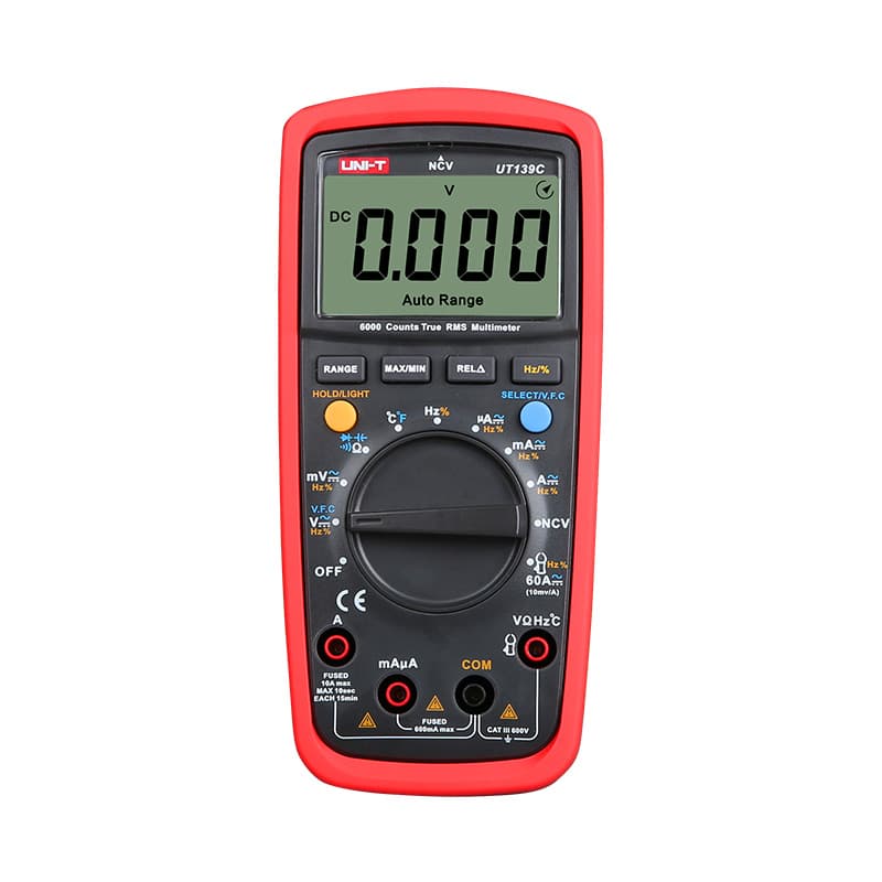
True RMS, 6,000-count, auto-ranging, CAT III 600V. True RMS and auto-ranging at a budget price.
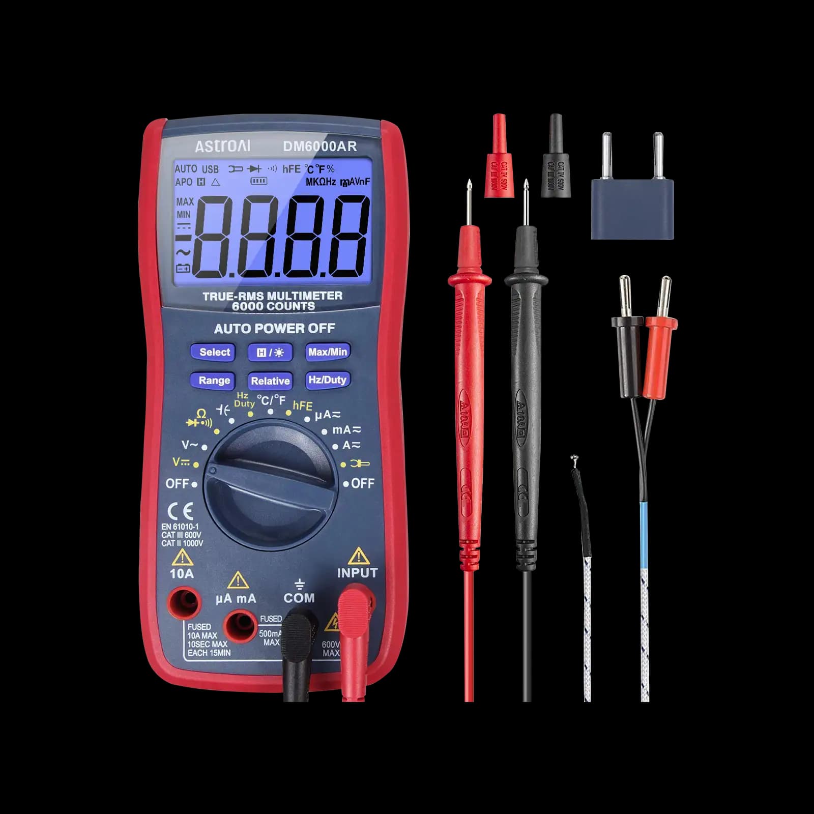
True RMS, 6,000-count, auto-ranging. Our pick for microcontroller and electronics projects.

True RMS, auto-ranging, CAT II 600V. Covers the fundamentals well: the sensible first meter.
As an Amazon Associate I earn from qualifying purchases. Prices and availability are shown on Amazon.
Frequently asked questions
Can a multimeter's diode mode light the optocoupler LED enough to switch the output?
Sometimes, but not reliably. Diode mode pushes only a small test current, often around a milliamp, and the output transistor may conduct a little or not at all. Some people try it with a second meter on the output, but a battery and resistor give a known LED current and a far more trustworthy result.
What is the current transfer ratio of an optocoupler?
The current transfer ratio, or CTR, is the output transistor current divided by the LED current, given as a percentage. A part with a 100 percent CTR passes about 10 mA at the output for 10 mA into the LED under the datasheet test conditions. CTR falls as the LED ages, which is why old optocouplers can fail weakly rather than completely.
Can I replace a PC817 with a different optocoupler?
Only if the pinout, isolation voltage, CTR range, speed and output type are suitable for the circuit. Many 4-pin phototransistor parts share the PC817 pin arrangement, but CTR grades and ratings differ, and a mains power supply needs a part with the correct safety approvals. Compare both datasheets before swapping.
Why does my optocoupler output read low resistance even with the LED off?
Out of circuit, that points to a shorted or leaky output transistor, and the part should be replaced. In circuit, the meter is usually measuring through other components connected across the collector and emitter, such as a pull-up resistor or a transistor stage. Lift the part or at least its output pins to be sure.
Do optocouplers wear out over time?
Yes, slowly. The internal infrared LED gives less light as it ages, and it fades faster when driven at high current or kept hot, so the current transfer ratio drops over years of service. A part that still tests fine on the bench can then fail to switch a marginal circuit. Good designs allow for this by driving the LED hard enough to keep the output saturated at a reduced CTR.



