HOW-TO GUIDE
How to Solder a Surface Mount Capacitor by Hand
By the OhmSavvy Research Team ·

Safety: stored charge, hot tips and tantalum failures
- Disconnect power and discharge large capacitors before working on a board. Power supply capacitors can hold charge after unplugging.
- A tantalum capacitor fitted backwards, or run above its voltage rating, can fail short and burn. Double-check polarity before you first power the board.
- Keep the iron in its stand when not in hand, use fume extraction, wear eye protection and wash your hands after handling leaded solder.
SMD capacitor types and package sizes
Most surface mount capacitors you will hand solder fall into three families. Ceramic chips use the same imperial size codes as chip resistors, such as 0603, 0805 and 1206; tantalum parts use case letters (A, B, C, D) defined by the manufacturer; aluminum electrolytics are cans on a plastic base.
| Type | Polarised? | Marking | Hand soldering concern |
|---|---|---|---|
| MLCC (ceramic chip) | No | Usually none | Thermal shock cracking; unmarked |
| Tantalum chip | Yes | Band = positive, often a value code | Polarity; failure if reversed |
| Aluminum electrolytic SMD can | Yes | Dark top segment = negative | Orientation; plastic base melts if overheated |
| Polymer / film chips | Varies | Varies by maker | Check the datasheet for heat limits |
| Imperial | Metric | Approx. L × W | By hand |
|---|---|---|---|
| 1206 | 3216 | 3.2 × 1.6 mm | Easiest; more thermal mass |
| 0805 | 2012 | 2.0 × 1.25 mm | Comfortable with tweezers |
| 0603 | 1608 | 1.6 × 0.8 mm | Needs magnification |
Why ceramic SMD capacitors crack when hand soldered
An MLCC is a stack of thin ceramic layers with metal electrodes between them. Ceramic is brittle and conducts heat unevenly, so when one corner is hit by a tip at soldering temperature while the rest is cold, the difference in expansion can split it. Those cracks usually start under or near an end termination, are often invisible, and may only show up weeks later as a short or a drifting value. Board flexing does the same after soldering, which is why parts near screw holes and edges crack more.
- Preheat the board on a preheater or with gentle hot air, especially for 1206 and larger parts, so the joint only rises a modest amount.
- Keep the tip off the body. Heat flows through the pad and termination into the part far more gently.
- Heat evenly and avoid running the iron hotter than needed; a moderate setpoint with good flux beats a hot tip held briefly.
- No twisting or levering. Hold the part flat with tweezers, and never nudge it sideways while one end is solid.
- Let it cool naturally. Don't blow on it or touch it with a cold tool.
1Identify the value before you fit it
Ceramic chip capacitors look alike whatever their value, and two strips of tape from different reels are indistinguishable once the parts are loose. Cut one part at a time from its labeled tape. If a part has escaped, measure it on a meter with a capacitance range before it goes on the board; our guide to checking a ceramic capacitor with a multimeter explains why readings from X7R and similar dielectrics can sit below the nominal value.
Voltage rating and dielectric are not visible either, so when replacing a failed part, take them from the schematic, the parts list or a matching board rather than guessing.
2Check tantalum and electrolytic polarity
The most common SMD capacitor mistake is a tantalum fitted backwards. On a molded tantalum chip, the band marks the positive terminal. On a diode, a near-identical band marks the cathode, which is negative. Anyone used to diodes instinctively puts the band on the wrong side.
Aluminum SMD cans mark the negative side with a dark half-moon on the top, and the plastic base plate has two corners cut off on the positive side. The board silkscreen usually shows a + sign or a shaded half; conventions vary between designers, so compare against the old part's orientation or a photo taken before removal.
3Solder the surface mount capacitor by hand
The placement technique is the same one used for chip resistors: tin one pad, hold the part with tweezers, reflow that pad, then solder the other end. It is explained step by step in how to solder surface mount resistors without hot air, so here are only the capacitor-specific adjustments. Use a tip roughly as wide as the end cap (see tip types), add flux to both pads, and keep the first-pad solder small so the second end doesn't have to fight a tilted part. With leaded solder, a setpoint around 300–330 °C is a typical starting point; lead-free usually needs more. Make each end in a few seconds and stop.
Large and high-value capacitors
A 1206 MLCC of several microfarads contains many electrode layers and can sink a surprising amount of heat, and decoupling capacitors often sit on pads joined to ground planes. If solder balls up instead of flowing, resist turning the iron up sharply. Preheat the board, use a bigger chisel tip, and add flux. Aluminum cans need care in a different way: the iron should touch only the metal tab on the pad, as the plastic base and rubber seal soften with heat. A dull, grainy result means the joint never got hot enough; our guide to fixing a cold solder joint covers reflowing it.
Bulging, cracked or burnt: spotting failed SMD capacitors
| What you see | Type | What it usually means |
|---|---|---|
| Domed or split top, brown residue at the base | Aluminum electrolytic | Dried out or vented; replace it |
| Fine line across the body, chipped corner | MLCC | Cracked; may be shorted or intermittent |
| Charred body, scorch on the board | Tantalum | Failed short, often from reversal or overvoltage |
| Looks fine, measures near 0 Ω | Any | Internal short; check out of circuit to confirm |
| Part warm on a powered board | MLCC or tantalum | Leaking or shorted; power off and investigate |
Replace, don't reflow, a suspect ceramic chip
For general capacitor checks beyond ceramics, see how to test a capacitor with a multimeter, and compare stations in our best soldering irons roundup.
Irons and rework stations for SMD capacitors
Hand soldering chip capacitors rewards an iron with steady temperature and fast recovery, so you can use a moderate setting and still finish each end quickly. Removing a capacitor is a different job: both ends have to melt together, which is far easier with hot air or two irons than with a single tip. For smaller packages and tighter spacing, see how to solder fine-pitch SMD components.
Tools for SMD capacitor work
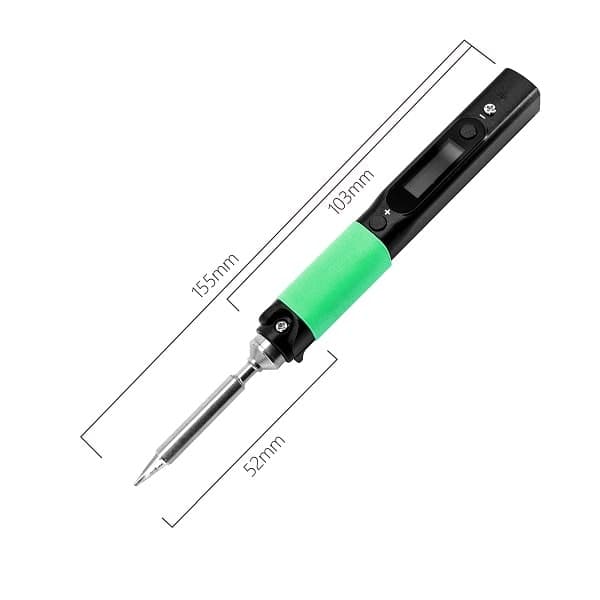
ESD-safe 100W station, 50–480°C, with presets so you can switch between small chip and larger bulk capacitor settings.
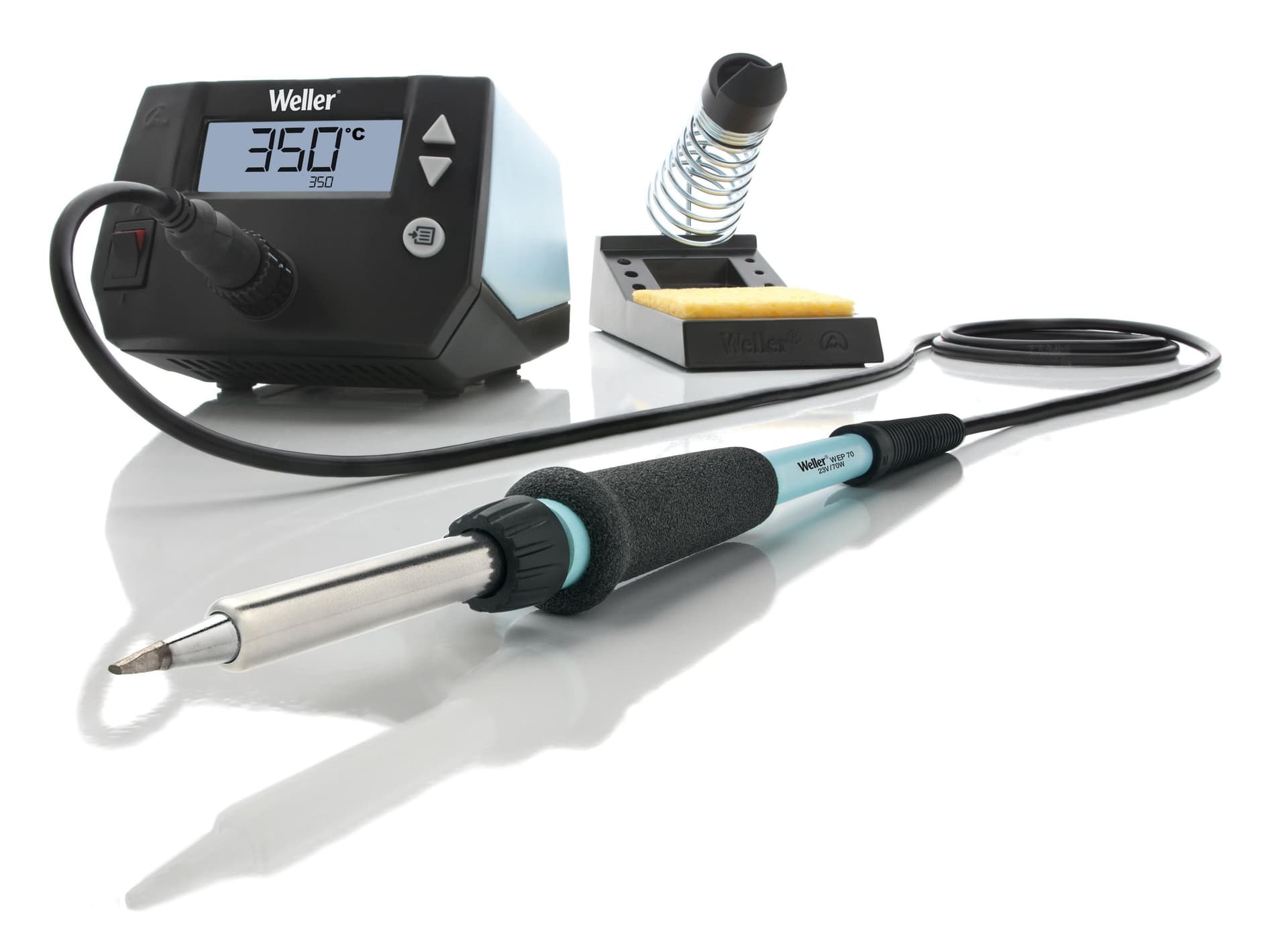
ESD-safe 85W digital station (70W iron) with tight temperature stability for repeated small SMD joints.
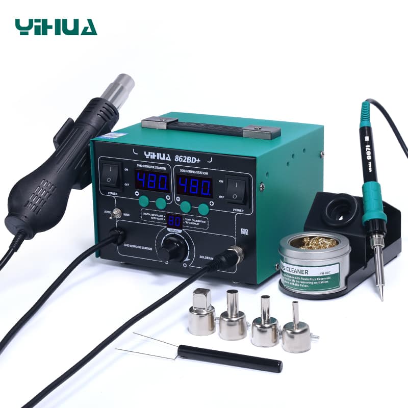
75W iron plus a 500W hot air gun with separate readouts, for lifting chip capacitors with both ends molten.
As an Amazon Associate I earn from qualifying purchases. Prices and availability are shown on Amazon.
Frequently asked questions
Which end of an SMD tantalum capacitor is positive?
The end with the band or bar is positive on a molded tantalum chip. That trips people up because a diode uses a similar band to mark its cathode, the negative end. Some polymer tantalum and niobium parts follow the same convention, but check the datasheet and the board silkscreen, which often shows a + sign or a shaded pad for the positive side.
Do ceramic SMD capacitors have polarity?
No. Multilayer ceramic chip capacitors are non-polarised, so they can go either way round. The things that matter are value, voltage rating, dielectric type such as X7R or C0G, and package size. Because MLCCs are almost never marked, keep them in their labeled tape or measure them before fitting rather than relying on color or appearance.
Can I reuse an SMD capacitor I removed?
It is better not to reuse a ceramic chip that has been removed with an iron. Removal heats it unevenly and often with mechanical stress, which can leave hidden cracks that cause a short or drift later. A tantalum or aluminum electrolytic part may survive, but fitting a new one costs little compared with chasing an intermittent fault afterwards.
Why won't solder stick to one end of a large capacitor?
Large or high-value MLCCs have a lot of internal metal that pulls heat away, and the pad may join a wide copper plane. The tip cannot bring that end up to temperature quickly. Use a larger chisel tip, add flux, warm the board with a preheater or gentle hot air, and let the joint come up evenly instead of raising the iron temperature sharply.
What does a cracked SMD capacitor look like?
Often nothing visible, which is the problem. Some cracks show as a fine line across the body or a chip missing near an end cap, but many sit under the termination. Signs include a capacitor that measures as a low resistance or short, one that gets warm on a powered board, or an intermittent fault that changes when you flex the board slightly.