HOW-TO GUIDE
How to Check a Ceramic Capacitor With a Multimeter
By the OhmSavvy Research Team ·

Power off and check for stored charge first
- Unplug the equipment before you measure anything. Ohms and capacitance modes only work on unpowered parts, and an external voltage can damage the meter.
- Small ceramics store little energy, but they often sit beside large electrolytic capacitors that can stay charged after power-off, especially in mains power supplies. Confirm close to 0 V across the supply rails before probing, and discharge large capacitors as described in our general capacitor testing guide.
- Ceramic discs connected across mains (often marked as X or Y safety capacitors) belong to the mains side of a circuit. Treat that area as live until you have checked it is not.
Ceramic capacitor types and how to read their markings
Most ceramic capacitors you will meet are one of three styles. All are non-polarized, so probe orientation does not matter for any test on this page.
Ceramic disc
Round, leaded, usually orange or blue. Common for small values and higher voltages; often printed with a code and a voltage.
Leaded multilayer
Small dipped blobs, sometimes called monolithic. Usually printed with a three-digit code.
SMD MLCC
Rectangular chips with metal ends. Usually unmarked, so the value comes from the schematic or parts list.
Printed values use a three-digit code in picofarads (pF): two significant digits, then a multiplier giving the number of zeros. So 104 means 10 followed by 4 zeros, 100,000 pF, which is 100 nF or 0.1 µF. An R marks a decimal point for small values, as in 4R7 for 4.7 pF. A letter after the code is the tolerance: J is ±5%, K is ±10%, M is ±20% and Z is +80/−20%.
| Code | Picofarads | Same value as |
|---|---|---|
| 4R7 | 4.7 pF | 4.7 pF |
| 101 | 100 pF | 0.1 nF |
| 102 | 1,000 pF | 1 nF |
| 103 | 10,000 pF | 10 nF |
| 104 | 100,000 pF | 100 nF = 0.1 µF |
| 105 | 1,000,000 pF | 1 µF |
Each step in the last digit multiplies the value by ten, which is why one meter range rarely covers every ceramic you will test. Small values are written without a multiplier on some parts: a disc printed just 22 is usually 22 pF.
Bars use a logarithmic scale: each step is ten times the last.
1Power off and isolate the capacitor
With the equipment unplugged and the rails confirmed near 0 V, decide whether you can test the part out of circuit. For a leaded ceramic, desoldering one leg is enough to break any parallel path. For an SMD chip, removal needs care: heat both ends together with two irons or a pair of hot tweezers, because levering one end while the other is still soldered can crack the part, the very fault you are looking for. If you have to test in circuit, read the pitfalls section below first and treat any result as provisional.
Look before you measure. Under a magnifier, check SMD chips for hairline cracks, especially running diagonally from the edge of a metal end, chipped corners, and dark or burnt spots on the body or the board beneath it. On a disc, look for a cracked coating or a scorched lead. A shorted capacitor on a powered rail often gets hot enough to discolor the board around it, so a brown patch near one part is a strong clue even when the part itself looks clean.
2Check for a short in ohms mode
Set the meter to resistance (Ω) and touch the probes to the two ends. A healthy ceramic blocks DC, so it should read OL, an open circuit. Small values charge from the meter's test current almost instantly, so you usually will not see the slow climb towards OL that a large electrolytic shows; a 1 µF or larger ceramic may show a brief climb first.
Shorts are the failure that matters most with multilayer ceramics. An MLCC is a stack of thin ceramic layers with interleaved electrodes; a crack from board flexing, a dropped device or thermal shock during soldering can let neighboring electrodes touch or leak. A shorted decoupling capacitor pulls its supply rail down to almost nothing, which is why a dead board with a near-zero-ohm rail is so often a single cracked chip.
3Measure it in capacitance mode
If your meter has a capacitance function, usually marked with the capacitor symbol or F, select it and connect the probes. Before measuring a small value, hold the leads in position without the part and use the meter's relative or zero function, if it has one, to subtract the capacitance of the leads themselves. Keep your fingers off the probe tips; your body adds capacitance too. Readings can take a few seconds to settle on larger values.
The weak spot is small values. On many general-purpose meters the lowest capacitance range is in the nanofarad region, so picofarad parts are at or below the resolution limit. If a range resolves 0.01 nF, a 100 nF part reads with plenty of digits but a 22 pF part shows only about 0.02 nF, and a few picofarads of lead capacitance is a large error on it. Your manual lists the ranges and resolution. For small timing and RF capacitors, a resistance check for shorts plus a like-for-like replacement is often more practical, and an LCR meter is the right tool for an accurate value.
C0G, X7R and Y5V: what reading to expect
The ceramic material, shown by a code on the reel, the parts list or the datasheet, decides how stable the value is. Class 1 dielectrics such as C0G (also called NP0) barely change with temperature or voltage and are made to tight tolerances. Class 2 dielectrics such as X7R, X5R and Y5V pack far more capacitance into a small part but drift much more.
| Dielectric | Class | Rated temperature range | Capacitance change over that range | Common tolerance |
|---|---|---|---|---|
| C0G / NP0 | 1 | −55 to +125 °C | 0 ± 30 ppm/°C | Tight, often ±5% or better |
| X7R | 2 | −55 to +125 °C | ±15% | Often ±10% (K) or ±20% (M) |
| X5R | 2 | −55 to +85 °C | ±15% | Often ±10% (K) or ±20% (M) |
| Y5V | 2 | −30 to +85 °C | +22% / −82% | Often +80/−20% (Z) |
Two more Class 2 effects matter when you compare a reading with the marking. Capacitance falls as a DC voltage is applied across the part, and on small, high-value MLCCs the drop at working voltage can be large; the datasheet's DC-bias curve shows how much. A multimeter measures with almost no bias, so it shows close to the full value, more than the part provides in service. Class 2 parts also lose capacitance slowly with age, so an old X7R reading a little low may be normal.
A rule of thumb for judging the reading
In-circuit pitfalls
Testing a ceramic capacitor without removing it is tempting, especially with tiny SMD parts, but the readings describe the circuit, not the part:
- Capacitors in parallel add up. Decoupling capacitors on one supply rail are all connected in parallel, so ten 100 nF parts read as roughly 1 µF whichever one you probe.
- One short shorts the rail. If one capacitor on a rail is shorted, every capacitor on that rail reads shorted. Lift them one at a time until the short moves with the part you removed.
- Resistors and chips confuse both modes. A resistor or an IC's supply pins across the capacitor give a finite ohms reading on a good part and upset capacitance mode. The same issue is explained in measuring resistance in a parallel circuit.
An in-circuit reading of OL with no short is useful evidence; anything else needs the part out of circuit before you decide.
Which meter to use for checking ceramic capacitors
Any multimeter with a resistance range can find a shorted ceramic. For values, you need a capacitance function, and its lowest range and resolution matter more than anything else for small parts. Among the meters in our best multimeters roundup, the Fluke 115's listing includes capacitance measurement; for other models, check the manual. The multimeter accuracy guide for electronics repair explains what display counts and accuracy figures mean for readings like these.
Meters in our reviews
True RMS, auto-ranging, CAT III 600V. The 117's reliability without NCV or LoZ, for field and electronics work.
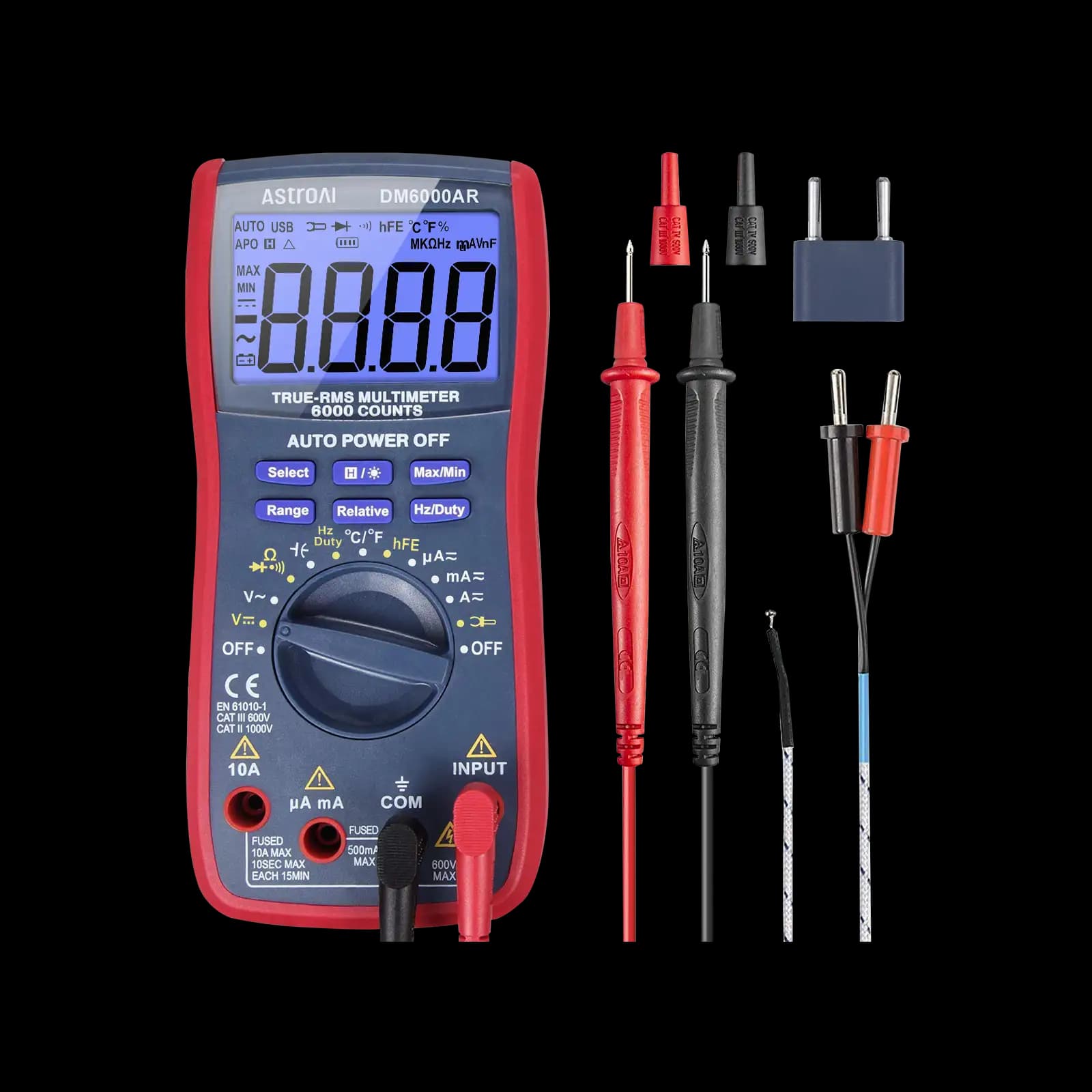
True RMS, 6,000-count, auto-ranging. Our pick for low-voltage microcontroller and electronics projects.
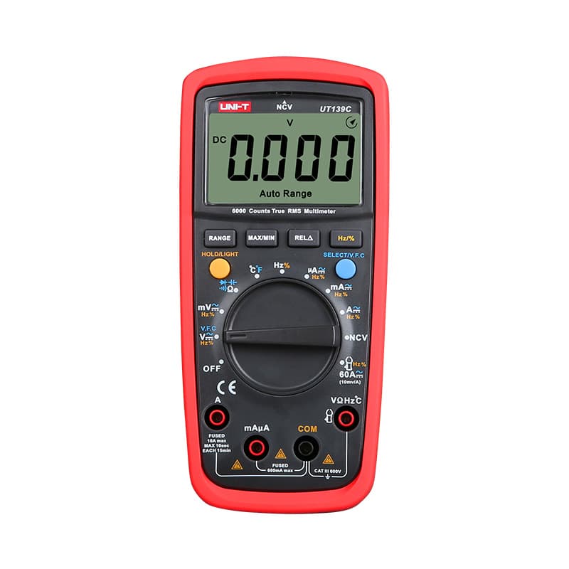
True RMS and auto-ranging with a 6,000-count display and a CAT III 600V rating, at a budget price.
As an Amazon Associate I earn from qualifying purchases. Prices and availability are shown on Amazon.
Frequently asked questions
What does 104 mean on a ceramic capacitor?
It is a three-digit code in picofarads. The first two digits are the value and the third is the number of zeros to add, so 104 is 10 followed by four zeros: 100,000 pF. That equals 100 nF or 0.1 µF, one of the most common decoupling values. A letter after the code, such as K, gives the tolerance.
Do ceramic capacitors have polarity?
No. Ceramic capacitors are non-polarized, so they can be fitted either way round and tested with the probes in either orientation. That is different from electrolytic and tantalum capacitors, which are marked with a polarity and can be damaged if reversed. If a ceramic-looking part has a polarity mark, check whether it is actually a tantalum.
Why does my multimeter read zero on a small ceramic capacitor?
Its value is probably below what your meter's lowest capacitance range can resolve. A 22 pF part is only 0.022 nF, which a range resolving 0.01 nF shows as about 0.02, and coarser ranges show 0. Test lead capacitance can also swamp tiny values. Use the relative or zero function with the leads in place, or use an LCR meter.
Can a ceramic capacitor fail without looking damaged?
Yes. Cracks in multilayer ceramic chips caused by board flexing, impact or uneven heating during soldering are often hidden under the end terminations or too fine to see. The part can look perfect while reading as a short or a resistive leak. A short across a supply rail that disappears when one capacitor is lifted is the classic sign.
Do ceramic capacitors lose capacitance over time?
Class 2 types such as X7R, X5R and Y5V do. Their capacitance decreases slowly with age, a known and specified effect, and heating them above a temperature given by the manufacturer resets it. Class 1 types such as C0G are essentially free of ageing. The manufacturer's datasheet gives the ageing rate for a specific part.


