HOW-TO GUIDE
Why Does Connecting an Oscilloscope Probe Change the Signal Being Measured?
By the OhmSavvy Research Team ·

What the probe looks like to your circuit
Every measurement takes a little energy from the thing being measured. A multimeter on DC voltage draws a tiny current through its input resistance; an oscilloscope probe does the same, but it also has to charge and discharge a capacitance every time the signal changes. Electrically, the probe tip, cable and scope input can be modeled as a resistance R in parallel with a capacitance C, connected between your test node and the point where the ground lead lands. The node you are probing almost never has zero source impedance, so it now drives a divider made of its own source resistance and that R ∥ C load.
The values depend on the probe. A general-purpose scope input is typically 1 MΩ in parallel with roughly 10 to 20 pF. A typical passive 10x probe adds a 9 MΩ resistor in its tip, so the circuit sees about 10 MΩ, and because the tip capacitance sits in series with the cable and input capacitance, the circuit sees only about 10 to 15 pF. A 1x probe has no tip resistor, so the circuit sees the bare 1 MΩ input plus the full capacitance of the cable and input together, often 50 to 100 pF or more. These are typical figures; your probe's spec sheet or the label on its BNC end gives the real ones. How the 10x tip divider is built is explained in how to compensate an oscilloscope probe.
Resistive loading: the reading drops
At DC and low frequencies the capacitor barely matters and the probe acts as a plain resistor. The voltage you see is the true voltage multiplied by R ÷ (Rs + R). On a low-impedance node, such as a regulator output, the loss is invisible. On a high-impedance node, such as a divider made from megohm resistors, a sensor bias point or the output of a high-value RC filter, it is not.
| Source resistance | Probe | Arithmetic | Shown |
|---|---|---|---|
| 10 kΩ | 1x (1 MΩ) | 1 ÷ 1.01 | 99.0% |
| 10 kΩ | 10x (10 MΩ) | 10 ÷ 10.01 | 99.9% |
| 1 MΩ | 1x (1 MΩ) | 1 ÷ (1 + 1) | 50% |
| 1 MΩ | 10x (10 MΩ) | 10 ÷ (1 + 10) | 90.9% |
A 1 MΩ source probed on 1x reads half its real value, which can make a healthy circuit look broken. The same node on 10x reads about 9% low. Neither is a scope fault; the scope is accurately showing the voltage that exists once the probe is attached. The same divider effect explains part of why a scope and a multimeter can disagree on the same node, which is covered in why a scope and a multimeter show different voltages.
Capacitive loading: edges slow down
As frequency rises, the capacitance takes over. A capacitor's reactance is Xc = 1 ÷ (2πfC), so it falls as frequency goes up. At 1 MHz, 15 pF is 1 ÷ (2π × 1,000,000 × 15 × 10⁻¹²) ≈ 10.6 kΩ, and 100 pF is about 1.59 kΩ. At 10 MHz those become about 1.06 kΩ and 159 Ω. Compare that with the 10 MΩ or 1 MΩ resistance, and it is clear that above a few hundred kilohertz the probe's "high impedance" is mostly a myth: a 1x probe at 10 MHz looks like a couple of hundred ohms to ground.
Bars use a logarithmic scale: each step is ten times the last.
In the time domain, the same capacitance has to charge through the source resistance every time the signal switches, which slows the edge. The 10% to 90% rise time of a simple RC is about t ≈ 2.2 × R × C. A logic output or pull-up with 10 kΩ of effective source resistance driving a 15 pF probe gives 2.2 × 10,000 × 15 × 10⁻¹² ≈ 0.33 µs. Swap to a 100 pF 1x probe and it becomes 2.2 × 10,000 × 100 × 10⁻¹² = 2.2 µs, nearly seven times slower. The equivalent bandwidth of that loaded node, 1 ÷ (2πRC), drops from about 1.06 MHz to about 159 kHz. A slowed edge can change timing, miss a logic threshold, or make a fast signal look like a triangle.
The probe also limits bandwidth on its own. A 10x passive probe is usually rated for the scope it ships with, often 100 MHz or more, but a 1x probe or a 10x probe switched to 1x is typically good for only a few megahertz to around 10 MHz, so edges look slower even on a low-impedance node. Check the bandwidth printed for each position on your probe. Rise-time measurement itself is covered in how to measure rise time with cursors, and the scope side of the equation in what oscilloscope bandwidth means.
Ground-lead inductance: extra ringing
The ground clip completes a loop from the tip, through the circuit, back along the ground lead. That loop has inductance, commonly estimated at around 100 to 200 nH for a typical clip lead of 15 cm or so, and it forms a series LC circuit with the tip capacitance. Its resonant frequency is f = 1 ÷ (2π√(LC)). With 150 nH and 15 pF, √(150 × 10⁻⁹ × 15 × 10⁻¹²) = 1.5 × 10⁻⁹, so f ≈ 1 ÷ (2π × 1.5 × 10⁻⁹) ≈ 106 MHz. Any edge fast enough to contain energy near that frequency rings at it, and the ringing is drawn on screen as if the circuit produced it.
A short ground spring has much less inductance, so the resonance moves well above the bandwidth of most hobby scopes and disappears from view. If you need to know whether ringing is real, the method is in how to measure overshoot and ringing; this page is about removing the part the probe adds.
Symptoms, causes and fixes
| Symptom | Likely cause | How to check | Fix or who to call |
|---|---|---|---|
| Voltage on a high-value divider reads low | Resistive loading by 1 MΩ (1x) input | Switch 1x to 10x; reading rises | Use 10x, or buffer the node; a 10 MΩ meter has the same limit |
| Square wave edges rounded on the circuit only | Probe capacitance charging through source resistance | Rounding changes between 1x and 10x, or at a lower-impedance point | Use 10x; probe a driven output; consider a low-capacitance probe |
| Rounded or peaked corners on the calibration output too | Probe out of compensation | Check the square wave on the scope's calibration terminal | Adjust the probe trimmer |
| Ringing on fast edges | Ground-lead inductance resonating with tip capacitance | Ringing shrinks with a short ground spring | Use a ground spring or tip-and-barrel connection |
| Oscillator stops or shifts when probed | Extra capacitance on a crystal or RC timing node | Circuit works when the probe is removed | Probe the buffered output; use 10x or an active probe |
| Fast signal much smaller on 1x | 1x bandwidth limit, often a few MHz | Amplitude recovers on 10x | Use 10x for anything above audio frequencies |
| Circuit misbehaves only when ground clip is attached | Ground clip creating a second ground path or shorting a non-ground node | Unclip the ground and check what it connects to | Clip only to true circuit ground; see the safety note below |
1Compare 1x and 10x on the same node
The quickest loading test is to measure twice. Note the amplitude and edge shape on 1x, then switch the probe to 10x, set the channel's probe factor to match, and look again. If the waveform changes shape or size by more than the scope's normal accuracy, the probe is loading the node, and the 10x view is the more trustworthy one. If the 10x reading still looks suspicious, the node is sensitive enough that even 10 MΩ and 10 to 15 pF matter, and the later steps apply.
01
Measure on 1x
Note amplitude and edges
02
Switch to 10x
Match the channel's probe setting
03
Compare
A change means loading
04
Reduce the load
Shorter ground, better node, better probe
2Shorten the ground
For anything with edges faster than a few tens of nanoseconds, take the long clip lead off. Most 10x probes come with a small spring or bayonet ground that slips over the tip barrel and touches a ground pad a centimeter or less away. If the board has no nearby ground, a short solid wire soldered to ground near the test point does the same job. The goal is the smallest possible loop between tip and ground. The basic attachment routine, including where the clip should go, is in how to connect an oscilloscope probe correctly.
3Move to a lower-impedance test point
The same signal often appears at several places in a circuit, and some are much harder to disturb than others. A driven output, the far side of a buffer, or the low side of a divider has a lower source resistance than a timing node, a crystal pin or the junction of two megohm resistors. Because rise-time slowing scales with R × C, moving from a 10 kΩ node to a 1 kΩ node cuts the slowing tenfold: 2.2 × 1,000 × 15 × 10⁻¹² ≈ 33 ns instead of 0.33 µs. With a crystal oscillator, probe the oscillator buffer or clock output rather than the crystal pins; the procedure is in how to check a crystal oscillator with a scope.
4Compensate the probe
A 10x probe only divides evenly across frequency when its tip capacitance is matched to the cable and scope input. Moved to a different channel or a different scope, it may not be. An undercompensated probe rounds the corners of a square wave much like capacitive loading does, and an overcompensated one adds overshoot that looks like ringing. Before blaming the circuit, put the probe on the calibration terminal and check for flat tops. If the corners are rounded or peaked there too, the problem is compensation, not loading. The trimmer adjustment is covered step by step in how to compensate an oscilloscope probe.
5Use the right probe for the node
A standard 10x passive probe is the right default for nearly all hobby and repair work. When even its 10 to 15 pF is too much, for example on a crystal pin, a high-speed clock or a very high-impedance analog node, an active FET probe typically puts only around 1 pF or less on the circuit, at the cost of a limited input voltage range and the need for power. Low-capacitance passive probes, sometimes called resistive divider or Z0 probes, are another option for fast, low-impedance signals and are meant for a 50 Ω scope input. For floating or mains-referenced signals, the right tool is a differential probe rather than a lower-capacitance one. Read the input range and capacitance on the maker's datasheet before buying any of them.
Probe ground is usually mains earth
1x or 10x: which to use
The 1x position exists for one reason: sensitivity. It is useful for very small, slow signals where the 10x divider would push the trace down near the scope's noise floor and the source can easily drive a 1 MΩ, high-capacitance load. For everything else, 10x loads the circuit less and preserves more bandwidth. The figures below are typical values for general-purpose passive probes, not specifications for any particular model.
| 1x (typical) | 10x (typical) | |
|---|---|---|
| Resistance seen by circuit | 1 MΩ | 10 MΩ |
| Capacitance seen by circuit | 50–100+ pF | 10–15 pF |
| Probe bandwidth | A few MHz to ~10 MHz | Often 100 MHz or more |
| Sensitivity | Full signal reaches scope | Signal divided by 10 |
| Good for | Small, slow, low-impedance signals | Logic, clocks, edges, most general work |
| Avoid on | High-impedance nodes, fast edges, oscillators | Signals of a few millivolts |
Whichever you choose, the channel's probe setting has to match, or every voltage reading is out by a factor of ten. Small-signal work on 10x is easier on a scope with fine vertical resolution, which is one place a 12-bit instrument helps.
In short
Scopes with bandwidth to spare for edge work
Four channels at 100MHz and 1 GSa/s, with a well-regarded, intuitive UI.
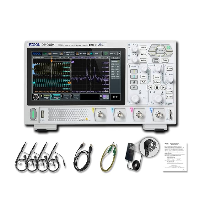
12-bit vertical resolution, 70 MHz and four channels, helpful for small signals on a 10x probe.

Four channels, 50MHz and 1 GSa/s on a large 7-inch display.
As an Amazon Associate I earn from qualifying purchases. Prices and availability are shown on Amazon.
Frequently asked questions
Why does my circuit stop working when I touch it with a scope probe?
The probe's capacitance, and on 1x its lower resistance, has been added to a sensitive node. Crystal oscillators, high-impedance bias points and weak pull-ups are the usual victims: an extra 10 to 100 pF can detune an oscillator or slow an edge past a logic threshold. Switch to 10x, probe a buffered output instead of the sensitive node, or use an active probe with lower input capacitance.
Does a 10x probe load the circuit less than a 1x probe?
Yes, on both counts. A typical 10x passive probe presents about 10 MΩ in parallel with roughly 10 to 15 pF at the tip, while a 1x probe presents only the scope's 1 MΩ plus the full cable capacitance, often 50 to 100 pF or more. The cost is a tenfold loss of sensitivity, so very small signals may sit near the scope's noise floor on 10x.
What is the input impedance of an oscilloscope?
Most general-purpose scopes have a 1 MΩ input in parallel with a small capacitance, commonly somewhere around 10 to 20 pF; the exact figure is usually printed next to the BNC connector and in the datasheet. Many higher-bandwidth scopes also offer a switchable 50 Ω input for matched cables. The probe you attach changes what the circuit actually sees.
Why does my square wave look rounded only when the probe is connected?
If the rounding changes when you switch the probe between 1x and 10x, or improves when you probe a lower-impedance point, it is probe loading: the probe capacitance is charging through the source resistance. If the corners look rounded or peaked on the scope's calibration output too, the probe is out of compensation, which is a separate adjustment made with the trimmer on the probe.
How much does a scope probe affect a high-impedance measurement?
It forms a divider with the source resistance. With a 1 MΩ source, a 1x probe on a 1 MΩ input reads half the true voltage, because 1 ÷ (1 + 1) = 0.5. A 10 MΩ 10x probe reads 10 ÷ 11, about 91%, so roughly 9% low. Above a few megohms of source resistance, even 10x loading is significant and a buffer or active probe helps.
Can a long ground lead change the waveform?
Yes. The ground lead is a small loop of wire with inductance, often estimated at around 100 to 200 nH for a typical clip lead, and it resonates with the probe's tip capacitance. Fast edges excite that resonance, so you see ringing that is not in the circuit. A short ground spring or tip-and-barrel connection pushes the resonance far higher and usually removes it.
Where to go next
How to Connect an Oscilloscope Probe Correctly →
Tip, ground clip and BNC connection basics before you worry about loading.
How to Compensate an Oscilloscope Probe →
The trimmer adjustment that makes a 10x probe's divider flat across frequency.
How to Measure Overshoot and Ringing →
Tell real ringing from the kind your ground lead adds.

