HOW-TO GUIDE
How to Test a Varistor With a Multimeter
By the OhmSavvy Research Team ·

Mains equipment: unplug, wait and discharge
- Varistors sit at the mains input of power supplies, appliances and surge strips. Only test with the equipment unplugged from the wall, never just switched off.
- Power supplies hold charge in their main filter capacitor after unplugging. Measure DC volts across it and wait or discharge it safely before touching anything; see how to test a capacitor for safe discharge.
- If you are not confident working inside mains equipment, stop and use a qualified repairer. Never power up a repaired device with the cover off.
What a varistor does
A metal oxide varistor is a disc of zinc oxide material between two electrodes, usually a colored blue, red or black disc with two leads. Its resistance depends on the voltage across it. At normal mains voltage it is very high, so almost no current flows and it might as well not be there. When a surge pushes the voltage above its rated level, its resistance drops sharply and it conducts heavily, clamping the spike and absorbing the energy that would otherwise reach the circuit behind it.
You usually find one connected straight across the incoming line and neutral, just after the fuse, and sometimes from each conductor to earth as well. Unlike a diode, a varistor is symmetrical: it behaves the same in both directions and has no polarity.
How they fail
1Unplug the equipment and discharge it
Unplug the device and remove the cover following the maker's instructions. On anything with a switch-mode power supply, find the large filter capacitor near the input, set the meter to DC volts and confirm it has discharged to a safe level before your fingers go near the board. Then locate the varistor: a disc near the mains connector and fuse, often labeled RV, VR, VDR or MOV on the board.
2Look for physical damage
Many failed varistors announce themselves. Look closely, with a light and a magnifier if needed, before measuring anything.
| What you see | What it means |
|---|---|
| Cracked, split or chipped disc | Failed; replace even if it measures open |
| Black scorch marks or a burnt smell | Failed after conducting a large current |
| Disc partly or completely missing | Blown apart; check the fuse and nearby parts too |
| Soot or carbon on the board around it | Clean thoroughly; carbon tracks can conduct |
| Bulged or discolored coating | Overheated; treat as suspect |
| Clean, intact disc | Proceed to the resistance check |
A failed varistor almost always takes the input fuse with it, so test the fuse as well. Our guide on testing a fuse without removing it covers in-place checks; with the board out of the equipment, a simple continuity test across the removed fuse is quicker.
3Check the resistance
In circuit, the varistor sits across the transformer primary or the power supply input, which may read anywhere from a few ohms to kilohms and hide a healthy varistor's high resistance. For a reliable result, desolder one leg and lift it clear of the board.
- Set the meter to resistance on its highest range, or auto-ranging.
- Touch the probes together to confirm a near-zero reading.
- Probe across the two varistor leads, holding the probes rather than the leads themselves.
- Reverse the probes and repeat. The reading should be the same both ways.
| Reading (leg lifted) | Likely meaning | Action |
|---|---|---|
| OL or very high MΩ, both directions | Not shorted | Passes this test; inspect visually as well |
| Near 0 Ω | Failed short | Replace, and check the fuse |
| Steady kΩ to low MΩ | Degraded or contaminated | Clean and retest; replace if it stays low |
| OL but cracked or burnt | Blown open | Replace |
If you cannot lift a leg, an in-circuit reading still tells you something in one direction. A reading of near zero across the varistor's pads is a strong hint that it, or something in parallel with it, is shorted, and lifting the leg then shows which. A high in-circuit reading is a pass, because the parallel parts can only lower the result, never raise it. A middling reading proves nothing until the leg is lifted.
If OL is new to you, see what OL means on a multimeter. A diode-mode test adds nothing here: unlike a diode, a varistor has no junction that conducts at half a volt, so it simply reads open in both directions.
Why a multimeter can't check clamping voltage
The property that matters most, the voltage at which the varistor starts to conduct, is hundreds of volts on a mains part. A multimeter's resistance mode tests with a small voltage, typically a few volts or less, so it never gets anywhere near the conduction point. That is why a good varistor and one that has drifted low with age can both read open.
Checking the varistor voltage needs a test that applies a controlled high voltage with a strictly limited current, such as a dedicated component tester or an insulation tester with a suitable voltage setting. That is specialist work with lethal voltages. For a repair, if a varistor is old, has seen a known surge or sits next to burnt parts, replacing it is simpler and cheaper than proving it is still within specification.
4Read the markings
Many disc varistors use a code like 14D471K. Manufacturers vary, so confirm with the datasheet, but the common scheme reads as follows.
01
14
Disc diameter, 14 mm
02
D
Disc type
03
471
47 × 10¹ = 470 V varistor voltage
04
K
±10% tolerance
The varistor voltage is normally the voltage across the part at a 1 mA DC test current, not the continuous voltage it can sit at. The datasheet lists a separate maximum continuous AC (RMS) voltage that is lower. Typical pairings for common disc codes:
| Code | Varistor voltage | Typical max continuous AC | Typical use |
|---|---|---|---|
| 241 | 240 V | ≈ 150 V AC | 120 V mains equipment |
| 391 | 390 V | ≈ 250 V AC | 230 V mains equipment |
| 431 | 430 V | ≈ 275 V AC | 230 V mains equipment |
| 471 | 470 V | ≈ 300 V AC | 230 V mains equipment |
5Replace like for like
Fit a replacement with the same varistor voltage and the same or larger disc diameter, provided it fits the board and its clearances. Disc size relates to how much surge energy the part can absorb, so a smaller disc is a downgrade. Do not fit a lower voltage part, which can conduct on normal mains peaks and overheat, or a much higher one, which lets bigger spikes through. If the marking is burnt away, the maker's parts list or an identical board is the safest source.
Match the construction too. Some equipment uses thermally protected varistors, which combine the disc with a thermal cut-off in one package, often with three leads, so a varistor that overheats disconnects itself instead of burning. Replacing one of those with a plain two-lead disc removes that protection. Mains-input parts on certified equipment may also need safety-agency approvals, which the original part's datasheet will list; choose a replacement that carries the same approvals.
Think about why the old part failed before you close the case. A single lightning-related surge on old equipment is one thing. A varistor that has failed more than once, or a burnt part on a device that runs from a generator, an unstable supply or the wrong mains voltage, points at a supply problem that a new varistor will not fix. A 120 V device fed from 230 V, for example through the wrong travel adaptor, will destroy its correctly rated 240 V varistor almost at once.
Keep the leads short, as the original was, and replace the fuse with exactly the same rating and type. Before reconnecting mains, check that there is no short across the input: a resistance check across the plug's line and neutral pins with the device switched on may show a few ohms or more through a transformer primary, but should not read a dead short. If the new fuse blows at power-up, something else is damaged, so stop and investigate.
Which meter to use for varistor checks
The resistance check itself needs nothing special. What matters is the rest of the job: checking the filter capacitor has discharged and, later, confirming the repaired device on the mains. For that, choose a meter with a safety rating suitable for mains work. The meters below are from our best multimeters roundup.
Meters in our reviews
True RMS, auto-ranging, CAT III 600V. The meter working electricians buy with their own money.
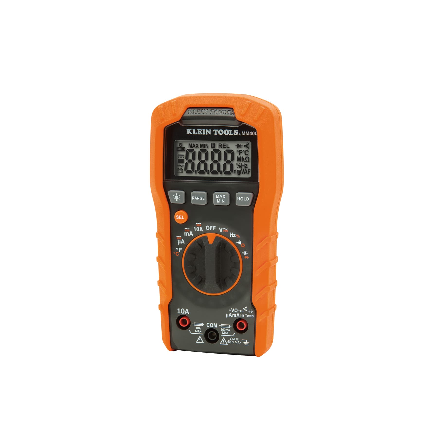
Auto-ranging, CAT III 600V, for tradespeople and home electrical work.

True RMS and auto-ranging with a CAT II 600V rating. The sensible first meter for home use.
As an Amazon Associate I earn from qualifying purchases. Prices and availability are shown on Amazon.
Frequently asked questions
Why did the fuse blow when the varistor failed?
A varistor that fails short puts a near short circuit across the mains input as soon as the device is plugged in, and the fuse in front of it blows to stop the current. That is the intended protection. Replace both parts, and look for why it failed, such as a surge, a lightning strike or a supply fault, before powering up again.
Can I run a device without its varistor?
It may work, because the varistor does nothing under normal conditions, but the device then has no protection against the next surge, and the next spike could damage more expensive parts. It is better to fit a correct replacement than to leave the position empty. Never bridge a blown fuse to get a device running.
Is a varistor the same as a thermistor?
No. Both are resistors whose value changes, but with different triggers. A varistor changes with voltage, staying high until a surge pushes it above its rating. A thermistor changes with temperature, and NTC types are often fitted at a power supply input to limit inrush current. They can look similar, so read the marking before testing or replacing.
Do surge protector power strips use varistors?
Many do. The varistors inside absorb surges and wear a little with each one, and many strips have an indicator that shows when protection is no longer active. Treat a strip with a failed indicator, scorch marks or a burnt smell as worn out and replace the whole strip rather than opening it to change parts.
How long does a varistor last before it needs replacing?
There is no fixed lifespan. A varistor that never sees a surge can outlast the equipment, while one on a supply with frequent spikes degrades faster. Manufacturers publish pulse-rating curves showing how many surges of a given current and duration a part tolerates before its voltage drifts out of tolerance. In practice, replace it when it shows damage, tests shorted or sits beside a fuse that has blown.


