HOW-TO GUIDE
How to Capture a Power Supply Transient With an Oscilloscope
By the OhmSavvy Research Team ·

What a load transient looks like
When load current jumps, the output capacitors supply the difference for the first moments, and the rail sags until the regulator's control loop responds. The loop then pulls the rail back, sometimes with a little ringing. When the load drops away, the opposite happens: the rail briefly rises above nominal. Two numbers describe the result: the undershoot (or overshoot) amplitude and the recovery time back to within a tolerance band. Start-up behavior is a separate test, covered in its own guide.
1Build a simple load step
An N-channel MOSFET switching a power resistor gives a clean, repeatable step. Choose the resistor for the step current you want (R = V ÷ I; a 5 V rail and a 1 A step needs 5 Ω), drive the gate from a function generator with a low-frequency square wave, and keep the on-time short so the resistor and MOSFET stay cool: at 1 A from 5 V the resistor dissipates 5 W while on, but at a 10% duty cycle the average is 0.5 W. A small resistor in the source leg lets you watch the current as a voltage. Connect the step close to the output capacitors, where the real load would sit.
2Probe the rail without picking up noise
The standard 15 cm ground clip forms a loop that picks up magnetic fields from switching regulators and adds spikes that look like part of the transient. Remove the probe's hat and ground clip and use a tip-and-barrel connection: the tip touches the positive terminal of the output capacitor, and a short ground spring wrapped around the barrel touches its ground terminal. This is the same technique used for measuring ripple voltage, and it matters just as much here. Turn on the channel's 20 MHz bandwidth limit to hold back switching noise; load transients play out over microseconds to milliseconds, so the limit removes noise without changing their shape much.
3Zoom on the rail: DC with offset, or AC coupling
A 100 mV dip on a 5 V rail is invisible at 1 V/div. You need around 20 to 50 mV/div with the rail centered on screen, and there are two ways to get there.
| Method | How | Strength | Weakness |
|---|---|---|---|
| DC coupling with offset | Set the channel offset to the nominal rail voltage, then raise sensitivity | Shows the true level, slow recoveries and load regulation | Offset range is limited at high sensitivity on some scopes |
| AC coupling | Block the DC level and raise sensitivity | Works on any scope, no offset needed | Distorts slow recoveries and hides the DC shift from load regulation |
Prefer DC with offset whenever the scope's offset range reaches the rail voltage at your chosen V/div; it is the only way to see that the rail settled at a slightly lower level under load, which is part of the answer.
4Trigger on the dip, or on the load-switch gate
With a controlled load step, trigger on CH2, the MOSFET gate, rising edge, Normal mode. The gate is clean, so the transient lands in exactly the same place every sweep and you can even average. For a transient you do not control, such as a dip caused by firmware switching something on, trigger on the rail itself: edge trigger, falling slope, level a little below nominal, Single mode. Only a real sag crosses that line.
5Measure undershoot amplitude and recovery time
Stop the acquisition. Put one horizontal cursor on the rail level before the step and the other at the bottom of the dip: the difference is the undershoot. Then decide on a tolerance band, such as ±1% of nominal or the regulation the load needs, and place vertical cursors from the load step edge to the moment the rail re-enters that band for good. Repeat on the falling edge of the gate for overshoot. Peak detect or a single capture shows the worst dip; averaging shows a cleaner typical response.
01
Step the load
MOSFET + resistor, gate from generator
02
Zoom the rail
DC offset, 20 to 50 mV/div
03
Trigger
Gate edge, or rail falling below nominal
04
Measure
ΔV undershoot, time back into band
Deep dip or slow recovery?
Input-side transients
Disturbances can also arrive from the input: a supply input sagging when a motor on the same source starts, a hot-plug spike when a connector is pushed in, or a battery dipping under load. Put CH1 on the input and CH2 on the output, trigger on the input with a falling edge just below its normal level (or rising for a spike), and check whether the output holds regulation through the event. For narrow input spikes, the techniques in capturing a brief voltage spike apply.
Troubleshooting a transient capture
| Symptom | Likely cause | Fix |
|---|---|---|
| Sharp spikes at every switching edge | Ground-lead pickup from the regulator | Tip-and-barrel probing and the 20 MHz limit |
| Dip appears to recover by itself even with a long load pulse | AC coupling high-pass effect | Use DC coupling with offset |
| Trace off screen after raising sensitivity | DC level not offset | Set channel offset to the rail voltage |
| Single never triggers on an uncontrolled sag | Trigger level too far below nominal | Move the level closer to nominal in small steps |
| Load resistor or MOSFET gets hot | Duty cycle too high | Shorten the on-time or lower the repetition rate |
Mains-powered supplies and hot loads
Scopes for transient work
Load-step testing benefits from more than two channels, so the rail, the gate drive and the sense resistor sit on one screen, and from fine vertical resolution when the dip is only tens of millivolts on a multi-volt rail.
Scopes for power supply transients
4 channels at 50MHz cover rail, gate and current-sense traces together at an approachable price.
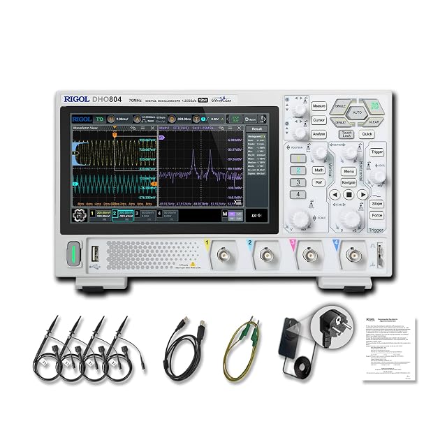
12-bit vertical resolution resolves small rail dips in finer steps than an 8-bit converter.

100MHz and 4 channels, with 500 MSa/s per channel when every input is in use.
As an Amazon Associate I earn from qualifying purchases. Prices and availability are shown on Amazon.
Frequently asked questions
How big a load step should I use?
Match what the real circuit does. If the datasheet of the load, or of the regulator, specifies a step such as 10% to 90% of rated current, use that. Otherwise step between the circuit's idle current and its peak current. A step larger than the regulator's rating tells you about current limiting, not transient response.
Does the speed of the load step matter?
Yes. A faster current step usually produces a deeper initial dip, because the output capacitors and their inductance carry the change before the control loop can react. Regulator datasheets often state the slew rate of their test step in amps per microsecond. Note your step's edge speed, visible on the gate or current channel, alongside the result.
Why is there a sharp spike at the very edge of the dip?
Partly real and partly measurement. The parasitic inductance of the output capacitors and board traces produces a sharp voltage step when current changes quickly. A long probe ground lead adds its own pickup on top. Re-measure with a tip-and-barrel connection right at the output capacitor; whatever remains is the circuit.
Can I use AC coupling to measure the recovery time?
For fast recoveries, yes. AC coupling blocks the DC level through a high-pass filter, so a dip that lasts a long time compared with that filter's time constant gets distorted and appears to recover on its own. If the recovery takes milliseconds, use DC coupling with offset instead.
How do I capture inrush current when a power supply turns on?
A scope measures voltage, so put a small, low-value sense resistor in the supply's input or output return and probe across it, or use a current probe. Current equals the measured voltage divided by the resistance. Set Single mode with a rising-edge trigger just above zero, choose a timebase of a few milliseconds per division, then switch the supply on and read the peak.

